Category Archives: Horizontal Stabilizer

Posts about the horizontal stabilizer

Closing Up the Horizontal Stabilizer

Completing the horizontal stabilizer went smoothly and turned out beautifully – ultimately. The fine folks at TAF, now Sling Aircraft, were super-supportive. Without going into great detail, I’d found that the leading edge bends of both HS skins were not on centerline – root to tip. They just wouldn’t fit properly – imposing significant stress and twisting of the structure. Sling Aircraft stepped up to quickly provide replacement HS skins and that saved the day.

I’ve been impressed with how precisely the holes in the skins match with the assembled structure. I’ve made a very conscious effort to take advantage of the kit precision. I try to get the skins initially positioned with very few clecos. I want to be able to move the skin slightly, until I can see that nearly all of the holes in the skin and structure are concentrically aligned. Starting the fitment process with fewer clecos makes that easier – possible. In practice, I’ve found that good overall initial skin position, relative to the underlying structure, allows the great majority of rivets to drop in – effortlessly. Once I’ve got the skin in place, I can further anchor things down with alternate clecos and hand-inserted rivets for the entire HS assembly.

I used a vertical HS working orientation that allowed me to evaluate skin fitment on top and bottom surfaces at the same time. Once the skin was in place, very few rivet holes needed attention – and then, only the slightest dressing with a chucking reamer in my lithium battery-powered drill. With a relaxed final fit of skin, rivets and structure – I’ve seen that when the rivets are pulled, nothing really moves. The permanently fastened skins are remarkably free of surface deviations. I’m quite pleased and anticipating that the contours of the final painted surfaces will be excellent.
HS Structure Assembly

The horizontal stabilizer assembly started by fitting together 2 sections of rear spar channel with the center section sandwiched by doubler plates – front and back. The result is over 8ft long. Appropriately sized cleco fasteners temporarily hold the parts together. A laser level helps to confirm that the channel is true – straight and free of twist.

The rear channel components were permanently fastened with a combination of 4.0 x 10mm and 3.2 x 8mm pulled rivets. Assembly continued with ribs joining with the front spar channel and clecos hold the front components as they are fitted and fastened in a similar fashion as the rear.

I’ve found that when 2 or 3 parts are sandwiched together with many rivets, it can be a little tricky to get a relaxed fit. Many overlapping holes must align precisely, in order for the rivet shanks to fit through all of the layers easily. I try to take whatever time is necessary to get the best concentric alignment of as many holes as possible, so that little or no reaming is necessary. The kit parts are punched very precisely and overlapping holes will likely line up, given the chance.

My assembly process starts with just a few clecos, while test fitting rivet shanks in many or most of the holes. Then I loosen and reset those few clecos until there is good natural alignment of as many holes as can reasonably be achieved. Eventually, a majority of the holes will line up perfectly, leaving only a very few that may need a little reaming to easily accept a rivet. Straight-shank chucking reamers seem to do a great job. Use the exactly right sizes. #30 and #20 are common.

The HS structure, without skins, is somewhat delicate. I’ve used a couple of stiffeners, from a Vans Aircraft workshop (skills practice) kit, clamped to the innermost HS ribs to provide support while the entire structure is riveted.

The HS structure is symmetrical. At some point, a decision must be made as to which side will be the top and the other side, therefore, the bottom. For my HS, continuity of how the rib flanges relate to the spar channels has turned out to be somewhat better on one side than the other. The side with the best potential for smooth skin support was chosen to be the top. I used a black permanent marker to make indications inside the front spar channel, where they can be seen during the various assembly phases.

With the HS top chosen, left and right HS panels become apparent. 2 Heyco 0.375in snap-bushings have been placed in the rear forming holes of the 2 innermost left-side ribs and anchored with some dabs of gray RTV. The nylon snap bushings are intended to protect the pitch trim servo wire (cable) as it passes through the ribs. I’ve elected to use nylon snap bushings instead of the rubber grommets supplied with the kit.

Horizontal Stabilizer – Prep and Prime

I’ve temporarily set aside the rudder and moved on to preparing the parts for the horizontal stabilizer (HS), after finding a poorly formed rudder hinge bracket, about a week before TAF folks returned from holiday break on January 13. Once they were back and after a few emails and phone calls – TAF (USA) has a new part on the way to me.

The preparation processes for the HS are the same as I’ve detailed for the rudder (RD). Several days of indoor and outdoor work have all the parts ready for assembly.

We got some snow and for a couple of days, it got too cold in the shop for painting. Inside the shop temperature dropped to 42 degrees F – overnight. I really needed more than my electric 1500W ceramic and 1200W infrared heaters.

I made a good deal a small portable propane heater and was able to continue with priming all of the HS parts. In the morning, I can bring the shop up to 60 degrees F in just a few minutes.

Starting Off On the Right Foot

I ordered my quick-build kit in July and I’ve had my empennage sub-kit since August, but have yet to pull my first rivet. I’m finding that it’s taking many hours for research and for me to learn enough background information to make confident choices that will set the direction and metrics I will endeavor to satisfy as I build. I think that’s part of the fun.

Surface priming – materials and techniques – is a significant matter. I’m still wrangling a bit with that, but have determined that I have to be practical, or I’m never going to put pen to paper, so to speak. My priming standards are going to fall somewhere closer to the minimum of bare aluminum rather than the extraordinarily high level demonstrated by the truly awesome work of Pascal Latten for his Sling 2 build. Spray painting can be a messy and tedious business. I’m not a professional and I want to keep things clean and simple as possible, while achieving a worthwhile result. In a nutshell, I’m going to use RustOleum self-etching aerosol primer for most internal mating surfaces. For more exposed areas, such as the hinge areas and outward facing structure of the horizontal and vertical stabilizer assembies, I’ll use Alumiprep 33 and Alodine 1201, coated with more durable PTI 2 part epoxy primer – and ultimately the final color top coat.

Wiring, VOR antenna and external lighting choices figure in early for the empennage build.

Aveo Engineering produces what I think is the best option for the anti-collision light atop the rudder. For reasons that included fit, features and color, I’ve opted for the aviation red Posistrobe MiniMax to complement Aveo 3-in-1 nav/position/strobe lights on the wingtips – exact model number of the wingtip lights TBD. Without a huge amount of work, and or ready access to a completed Sling 2, it’s really mostly an educated guess that the overall lighting results will satisfy FAR 23.1385 – 23.1401. Hopefully it will and the DAR will agree.

Rudder Cap Strobe Mounting Area – small, even for the 1.74in wide MiniMax Light

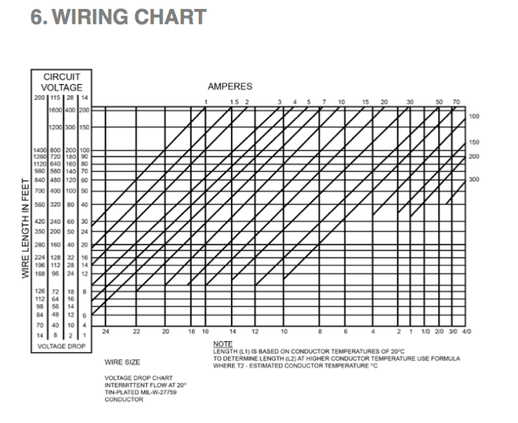
Working through the electrical current requirements of the LED rudder strobe against AC 43.13B, I’ve tried to determine the necessary gauge and then acquire M27500 shielded cable to replace the TAF-supplied PVC jacketed wire in the kit. Based on actual experience with such wire in my Warrior, I’m not impressed with its suitability for aircraft applications. Based on my calculations, I think readily available 22 gauge conductors would be sufficient to handle peak current less than 3A over a run of 20ft. But, based on some data from the awesome builder I mentioned earlier, it’s possible that 20 gauge wire would be a better choice. I ordered some M27500-20TG4T14 from WireMasters. The minimum order was 100ft. This wire may turn out to be overkill for the small LED light. We’ll see.

You’ll find a chart like this in AC 43.13B

The VOR/GS antenna gets built into the vertical stabilizer, so I have to make a commitment to that, even before I’ve settled on my avionics choices. I’m hopeful that conformance with FAA TSO: C34e, C36e, C40c will make my choice compatible with whatever I finally choose for a VOR/GS receiver. Keeping the antenna price down will also make it easier to go with only a GPS navigator. At least the antenna and wiring will be in place. I’ve opted for the Rami AV-520 which has 2.5in diameter base “puck” with removable whips, built-in balun and coax connection.

I’m aiming for an advanced IFR all-Garmin EFIS panel with autopilot. We’ll see where it ends up.

I’ve ordered a bunch of stuff and it will be here next week. I’m perilously close to the official start my Sling 2 build.