Category Archives: Fuselage

Iterate and Repeat

It’s important to keep making progress and not get bogged down on any one thing – like wingtips. Oh those wingtips! Will they ever be done?

Parachute, flaps, ailerons, seats, control sticks were all calling for attention. It was well worth spending time on to those things. Circle back to composite work later.

Much of the work is pretty straightforward. Other items require a bit of faith and commitment – like finalizing the riveting of ailerons and flaps closed, for example. Getting the control surfaces locked down with rivets and while maintaining alignment with the wing, is both science and art. I think maybe there’s a good bit of luck involved too.

Chopping off the control sticks is somewhat a leap of faith. The KAI doesn’t say to do that, but the Tosten CS-8 grips need to be in the right spot. They’re different than the push-on type that is typical for Sling 2s. You just gotta do what you gotta do.

Figuring out what to do with the parachute cables has been an exercise. There is almost no guidance from the factory. I asked them directly and they admitted that the factory rarely installs parachutes in Sling 2s they build there, and haven’t for a long time. There’s an old video. I’ve watched it repeatedly.

The one actual attempted in-flight deployment of a parachute-equipped Sling 2, ended in failure – loss of the aircraft. Fortunately, that was during factory testing and the pilots had their own parachutes – which they needed. That sad outcome reportedly resulted in consultation with the Stratos 07 parachute company. Changes were made and presumably incorporated in my kit. It is, nevertheless, clear to me that a builder could easily insure a complete tangle of the parachute and cables during a deployment. I’ve studied photos of several other Sling 2 parachute installations and identified things I thought could be problematic. I’ve tried dress and secure the cables to allow the best fighting chance for the parachute canopy, shrouds and airframe-cables to deploy without hindrance or entanglement. My guess is probably as good as anybody’s. Maybe better.

The weather is getting rather nice. Competing interests punctuate my days.
Some of This and Some of That

There’s lots of composite work to start and finish – and no shortage of details that need attention in the center and forward fuselage. It’s time to fit wheel fairings and prepare the compartment for the whole-aircraft ballistic parachute. The wingtips are getting closer. What a job those have been.

Windscreen Bonding

Bonding the windscreen is a critical milestone. It isn’t nearly as glamorous as mounting the engine or powering up the avionics, but it means a great deal to the overall aircraft structure and final outcome of the project. It’s a make or break moment.

Surface preparation of the bonding surfaces is very important. Various special primers promote adhesion. Accurately locating the about-to-be-bonded windscreen while things are battered with jet-black SikaFlex polyurethane marine adhesive, onto the frame and fuselage, is aided by reference holes and locating pins. Masking and protecting areas where adhesive does not belong, makes it just possible to get the assembly together without too much of a mess. Gentle, even clamping keeps the windscreen in place while the adhesive cures.

Minimum working temperature for the adhesive is 50ºF. At that temperature it will take up to 12 days to cure and it will be all I can do to keep my workshop warm enough though the winter days, here in Pacific Northwest Washington. Time will tell.

All in all, it seems like I’ve pulled it off! Looks like a good fit, no Plexiglass cracks and plenty of nice adhesive in the right places. Now I just hold my breath for a couple of weeks. Whew! Glad to have this step in my rearview mirror. What a relief.

Windscreen – Trim to Fit

Having put this off as long as I could, I’ve summoned the courage to trim the windscreen until it fits. I absolutely do not want to crack it and I cannot afford to over-trim. It has to be done, just so. If ever there was a time to apply, measure twice, cut once – this is it!

Along the way, I take comfort in and from small stress-reducing distractions. Testing out my fancy new lithium battery charger yields a few moments to gather myself. The charger has a feature that can supply up to 10A of current to power the avionics and allow for extended sessions of testing, configuration and familiarization – ok, play! There’s a lot to learn and it’s going to take quite a bit of play time.

Canopy Latch and Exhaust System

The canopy latch is inset within an oval area that must be carved out of the top front of the canopy plexiglass and underlying composite frame and held in place with blind M5 rivnuts and screws. Let’s just say that this is a challenging and nerve racking set of tasks. And – that’s a major understatement. But, with patience and a good bit of careful work with my trusty Dremel tool, I was able to achieve what I deem, at this point anyway, a satisfactory result.

The latch mechanism is an over-center affair with a hook engaging a latch pin that mounts to the top underside of windscreen support arch. Four 3,2 x 10mm CSK rivets attach the pin and it’s mounting plate to the arch, along with whatever additional security is afforded by a dollop of JB Weld epoxy. Where exactly to position the pin is an exercise left entirely to the discretion of the builder. Good luck with that.

I think by the time I get the weather seal in place, the latch will pull the canopy closed – firmly and without gaps. We’ll see. All of this latch fitment has happened before having the windscreen and support arch bonded in their forever positions. I’ve got my fingers crossed. Time will tell.

The exhaust system has been languishing in a box and it seemed a good time to see how well (if) it fits with the engine and airframe. It looks… maybe not so bad. Good!

There’s going to be some work needed to get the cabin heat muffler shroud assembled, because I don’t have a part that actually fits. So far, I’ve gotten 2 different parts (and part numbers) from the factory, but neither part matches the mounting rings on muffler. Argh. I’ll have to adapt and/or fabricate something. But, at least it seems the exhaust pipes and muffler do fit. Hooray for that.

Windscreen and Canopy – Initial Fit

Rivets, wires and avionics are friendly territory for me, compared to where I’m headed now. Fitting the windscreen and getting it bonded in position are tasks I’ve been apprehensive about – extremely apprehensive.

Manipulating clear acrylic sheet – Plexiglass and Perspex are brand names – that’s been molded into compound curves of unusual size, is just asking for trouble. I don’t like trouble. Dealing with this stuff is tricky, all by itself. Don’t even get me started about cutting or drilling holes in it. Eventually, I’m going to add sticky gooey pitch black marine adhesive caulk to the mix. That could easily lead to – yes, you guessed it – super trouble!

The time has come. I can’t avoid it any longer.

Because I opted for a factory quick-build kit, it came with the main canopy already trimmed and bonded to its painted composite frame. That’s fortunate because it may well have spared my frazzled nerves just enough to be able to deal with the windscreen.

The initial canopy placement seemed easy enough. Screw holes in the frame aligned with the ones in the slide assemblies. Countersinking of the frame will be needed to correspond with the short M8 stainless steel CSK mounting screws.

The arched windscreen support frame was fitted and match-drilled to align with M5 rivnuts that were installed at the factory. I made cardboard templates for left and right sides because they’re different. (They shouldn’t be – but that’s how the factory built it.)

The trial fit reveals that the rear edge of the windscreen will have to be cut back by at least 4 or 5 cm to align with the arched support frame. The lower rear edges (corners) of the plexiglass will just barely be under the fuselage top skin when it’s riveted in place. Precise positioning of the windscreen is going to be extremely important to avoid any unsightly gaps between the aluminum skin and the plexiglass.

A latch mechanism has to be fitted into the canopy. I inventoried the latch parts when I received them, but I could not have detected that the supplied spring was not correctly formed. I checked with the factory and confirmed the situation. They’re going to send me a replacement spring.

Windscreen cutting, drilling and bonding comes next.

Glareshield/Dash and Instrument Panel

I’ve been working hard to finalize work behind the instrument panel before I permanently close up the area and bond the windscreen in place. Once that happens, any work behind the panel will have to be done though the openings where the GDU 460 displays go. I could possibly remove the whole panel from the dash, but it’s really and truly so nestled into place that I don’t want to disturb it. Disconnecting it, reconnecting it, pulling it out and fitting it back seems more challenging than I want to contemplate — or actually deal with. Get everything right before it all gets locked down – that’s the plan.

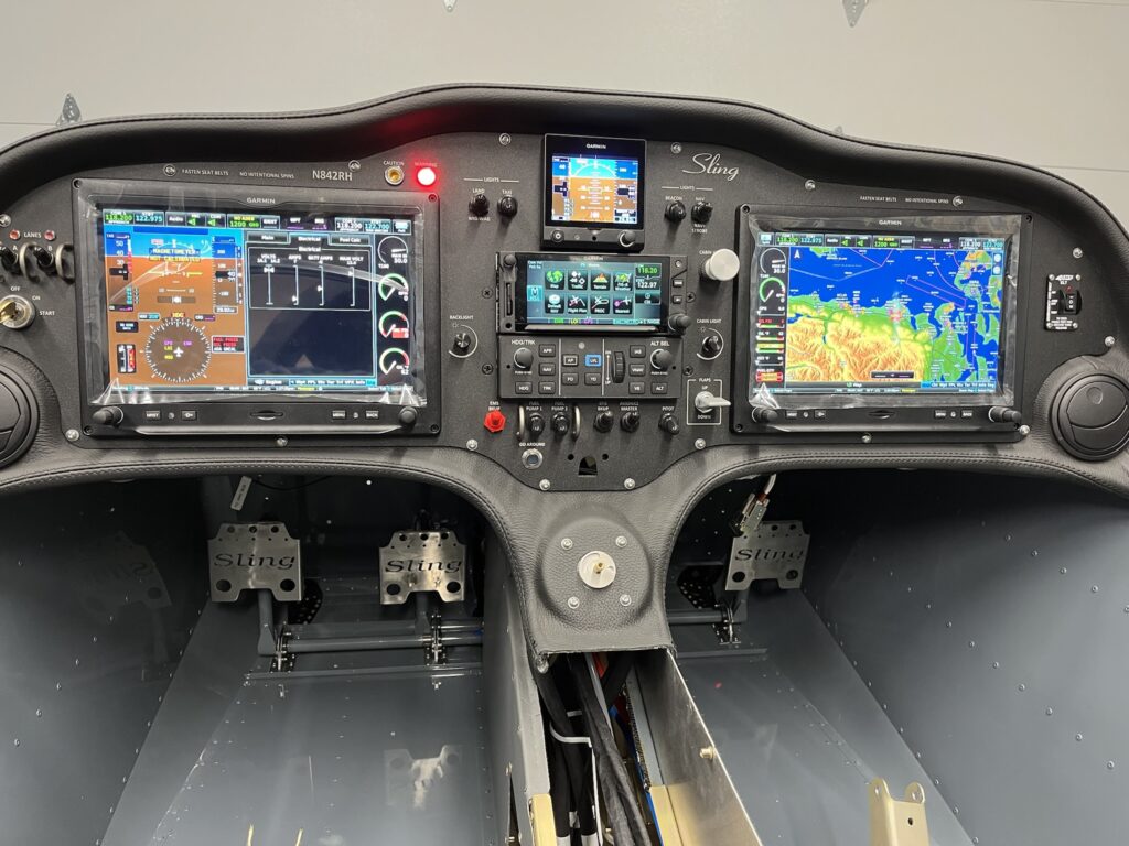
Instrument Panel Powered Up with Engine Information System (EIS) Displayed

The fuselage top-skin on my factory QB came partially riveted in place. I removed it. I also dimpled the skin and the rib to accept 3,2 x 10mm countersunk rivets. The parachute compartment cover skins will eventually go over the countersunk rivets, to be held in place by just a few domed rivets and slotted “fingers” at the edges of the cover skins. I’ve put the top skin back into position with clecos. The dash has been positioned and match drilled with the skin to accept 3,2 x 8 mm domed rivets. The lip of the dash is bonded to the skin with very sticky double-sided tape – supplied with the kit. The next step is to pull the rivets on the lip of the dash.

Once the dash lip is riveted, it’ll be time to fit the windscreen. The windscreen has to transition from outside to inside. The dash does the same thing. The windscreen needs to go between the dash and the skin at the edges. It’s going to be tight. I probably won’t rivet the skin until, or even perhaps after, I do the bonding process for the windscreen with Sikaflex adhesive.

Before bonding, the windscreen and support arch must be fitted with the canopy. The windscreen will almost certainly need to be trimmed along the rear edge of the arch. It’s all going to be very delicate and require great care. If I crack or otherwise damage the plexiglass windscreen it would likely be many months before I could get another one.

At this point, I’ve managed to get the panel and dash positioned and connected to the harness. The wiring looks crazy. Ok, it is crazy. But, it’s pretty much the nature of the beast. This is a custom plug-n-play harness that’s essentially one piece. I laid it into the CF like a sleeping octopus. There’s extra craziness because of how much stuff I’ve got to connect. I think the only way to make it any neater would have required building the harness on the airplane. That just couldn’t happen. As it is, I’ve got all of the various “tentacles” dressed and secured about as naturally and as stress free as they can be. I’m very happy with it, even if it looks rather wild. There’s a lot there.

I’m delighted to report that once again, the panel has life. This time, the Engine Information System (EIS) is active. The sensors seem to be working. There are still things that aren’t connected yet. But for the things that are, it all looks great and my confidence is high.

So far, working the flap control, hearing the actuator run and seeing the indicator change is my favorite thing. The VP-X Pro and the G3X Touch integration seem nice. Working the radio frequencies and the remote audio panel is very cool. Both radios transmit and receive. The headset jacks are working, but I haven’t been able to try the LEMO connectors yet. Navigation, position and strobe lights work. Cabin lighting works. Oh so nice.

I’ve got to say, it’s more than just a little exciting. Build on!

Fuselage Tasks – Cables, Wire and Lines

For an E/A-B project there’s a seemingly endless list of small tasks. Some things are simply items in the KAI. Other tasks are things that come to mind as you think about how its all going to come together. Task creep just seems to happen. As long as it doesn’t get out of hand – it’s a good thing.

There is a daunting amount of wiring to support the avionics I’ve elected to squeeze into this airplane. Frankly, I’ve gone overboard. On the other hand, I’ve got all of the makings for a technologically advanced airplane (TAA), extremely well equipped for IFR training and cross-country adventuring. Finding good ways to dress and secure the wiring bundles is important. I’ve put a lot of thought into it and determined that an extra bracket will help me keep the harness up and out of the way. I designed and fabricated one.

Many things have to be squeezed into available space without undue conflict. Wiring, fuel lines, pneumatic lines, brake lines, valves, linkages and such. While there are plenty of best practices for how to do things in airplanes, finding ways to apply them to all of the situations that present themselves is what keeps this amateur builder scrambling for ideas. There’s always something new to learn. It’s fun. Challenging, but fun. Yes. It is. I think.

The fuel-injected Rotax engine has a somewhat complex fuel system. The fuel lines have a fuel supply circuit and a fuel return circuit. When you add filters and a duplex fuel selector and physical considerations, the plumbing details border on outrageous. How I do it is up to me. The KAI supplies only general information. I’m also introducing AN6 flare and push-lock swivel fittings in several places where barbs and ear clamps were originally called out and supplied. Figuring out where and how to mount and connect many of the fuel system components is ongoing.

Some tasks just need doing. Then they’re done. Cutting coax cables to length and adding connectors is straightforward enough. Done. The Rotax 30A Regulator B needs a heat sink that calls for the regulator to move from the fusebox to a nearby location on the engine mount. Done. There are a couple of GPS antennas for the PFD and G5 flight instrument that found homes on top of the GAD 29, above the center avionics stack.

Brake lines need to be routed. The time to do it was now. One line goes from the brake fluid reservoir, through the firewall, to just under where the throttle and brake quadrant is located. From there, another line originates at the pressure side of the master brake cylinder an runs to a compression T-fitting under the console compartment. Two other lines run from the T-fitting, down the main gear legs to each wheel. The combination of the 3 lines and the T-fitting were challenging to place. I should have done it earlier, when access was better. It’s done now.

I received some [evidently] old-style mounting hardware for the parachute activation handle, so I ended making a small bracket to secure the activation pull-handle to the back of the instrument panel. It’s nice. It’s done. My design turned out to be a slightly improved version of a bracket I eventually saw in a photo from the factory. Great minds think alike.

It was time for pneumatic lines to go in. I found a really nice way to route them from the left wing root, though the center console and up behind the instrument panel. Because I’ve seen that the Sling TSi documentation now shows 2 static ports, I added a second one in front of the LH fresh air NACA duct. Both of the equal length static port lines arrive at a push-to-connect T-fitting at the center console. A short line runs from the first tee to another T-fitting that provides two more equal length lines to the the G5 and to the GSU 25C ADAHRS unit. The pitot line has a single T-fitting that also splits between G5 and the GSU 25. The AOA line only goes to the GSU 25. All done.

WAAS GPS and COM 1 Antennas

Quite a few Sling 2 aircraft have been built with their GPS antennas mounted on a bracket under the engine cowling. That’s how the factory used to do it. Now guidance has been changed and a location on top of the rear fuselage is preferred. The new location reportedly offers consistently better reliability. I want reliability for IFR flying.

It was no simple task to get RG-400 coax cable for the GPS routed – and satisfactorily secured – on its way from the top-rear of the baggage area, down and then forward along the bottom of the rear fuselage to the center fuselage, and on to finally arrive behind the GTN 650Xi on the instrument panel. It’s done and it worked out very well.

Dealing with the COM 1 antenna coax cable was comparatively easier than for the GPS because the factory-supplied coax was already secured in place, routed from the mounting site on top of the rear fuselage, all the way to the instrument panel area. All I had to do was add the connectors.

The GPS antenna needed holes drilled in the fuselage skin. I used a doubler that came with my panel and harness and the screws provided with the Garmin GA 35 antenna. A TNC 90 degree solder/crimp connector by Amphenol made for a tidy connection at the top rear of the baggage compartment. A section of vinyl hose, covered with black heat shrink, provides good protection and satisfying aesthetics where the coax passes through the bulkhead, into the rear fuselage.

The COM 1 antenna needed 4 existing mounting holes to be expanded, in order to accept setting of rivnuts. The KAI called for M4 but the Rami antenna, supplied as part of my custom avionics package, came with 8-32 screws. I decided to set 8-32 rivnuts into the fuselage for this mounting. The way the coax was secured to the internal fuselage structure lent itself more to a 90 degree BNC connector. Again I selected an Amphenol solder/crimp part.

CF – Upholstery, Painting & Wiring

Upholstery work takes a bit of courage and determination – at least for me it does. A big part of the work involves trimming the vinyl leatherette-like covering to fit the center console and then bonding pieces of material to some rather sizable and awkwardly shaped panels – everything is frighteningly sticky with spray adhesive.

I got through it and it all seems to look rather nice. I can’t say I’d do it the same way again, but at the same time, I don’t exactly know what I’d have done differently. You’ve just got to do the best you can.

All of the center upholstery pieces came in a kit, along with fiberglass-backed side panels, seat and seat back cushions, and carpet panels for the floor and luggage compartment. The seats cushions are covered with genuine leather and stitched by professionals. I got to choose the colors. Methinks it’s going to be a rather sporty and plush setup for this little 2-seater. Oh well! What can I say?

Once the rear portion of the center console was covered, it seemed a good time to put it into position. The inside seatbelts pass through, so it was time to assemble those to their anchors. I haven’t riveted the rear console yet – just clecos for now.

The front console panels have 3 sections. The top panel of the LH side is removable for inspections, as are 4 other square panels – 2 of which are covered with the vinyl. The 2 forward most panels are painted, along with 2 panels for the baggage area.

Bonding the covering to the RH side panel was the biggest challenge. The section of material was large enough to be unwieldy. Working conditions inside the CF were awkward. I did, however, manage to lay in the material and get it satisfactorily positioned. I’m happy to have that task in my rearview mirror.

This seemed a good time to complete more of the wire connections to the rear fuselage (RF) section for the tail beacon and electric pitch trim servo. The PVC jacketed wires in the RF were routed and secured as part of the factory quick-build (QB). My custom avionics harness was provided with “pigtail” connectors. I connected the wires of the pigtail to the fuselage wires with Raychem D-436 series butt splice connectors. The connectors are a bit expensive and a special crimp tool is required. I believe the resulting connections are more than satisfactory. As usual, I insulate and protect the connections and secure them from movement.