
There’s lots of composite work to start and finish – and no shortage of details that need attention in the center and forward fuselage. It’s time to fit wheel fairings and prepare the compartment for the whole-aircraft ballistic parachute. The wingtips are getting closer. What a job those have been.
Category Archives: Main Landing Gear
Wheels On
There’s not a whole lot to say except that the wheels are on!
The factory-supplied Matco wheels and brakes seem quite nice. I’d mounted the tubes and tires some time ago. I’ve packed the main wheel bearings with grease that came with the kit. The nose wheel has sealed bearings. I prepped the wheel fairing mounting brackets and treated them with alodine.
Jacking the airframe was a bit challenging. I’ll have to find a better way to do it for inspection and maintenance. Assembly went well.
It’s very good to see the thing up on its wheels.
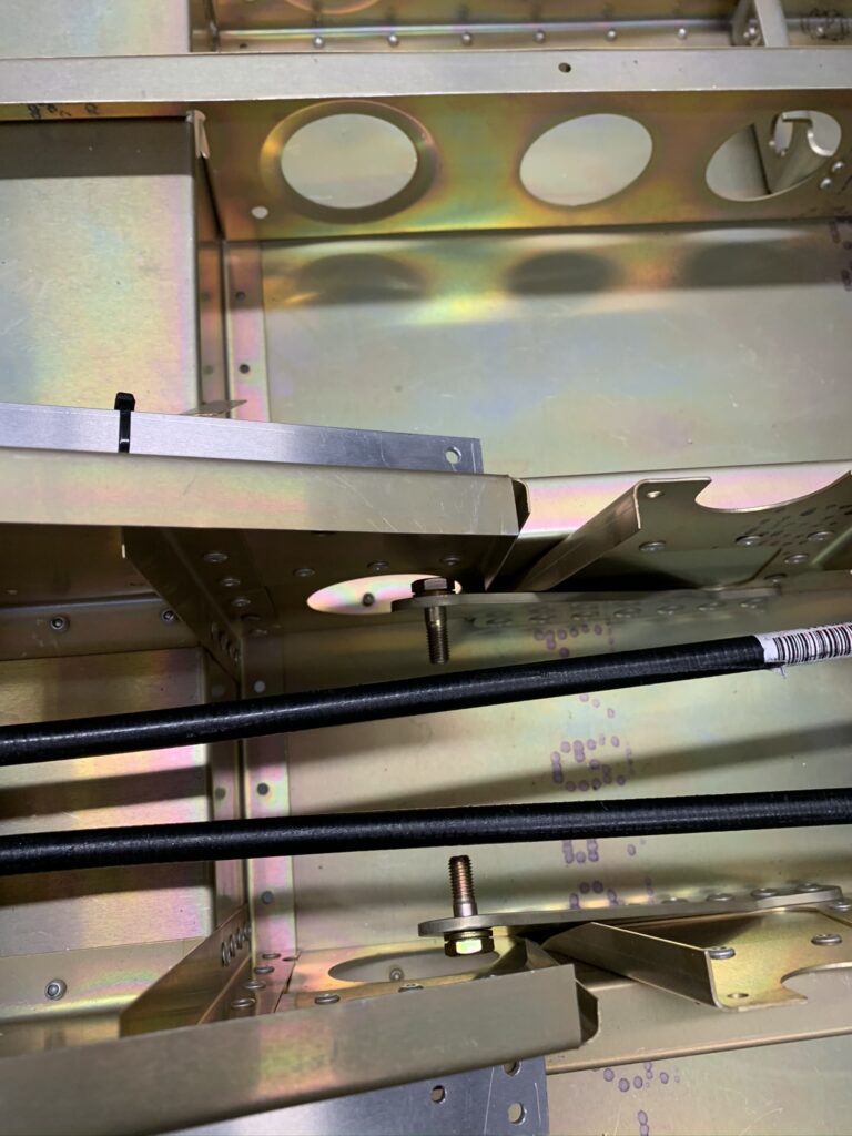
Fuselage Sitting on Main Landing Gear
It may not seem like a big deal, but having the fuselage safely off of the workbench, where it had been (somewhat precariously) perched, is a great relief and a meaningful milestone. It’s now in a position where I can work inside the center fuselage – comfortably and confidently.
The fuselage spent months sitting on the wooden structure that held it inside the sea shipping container. Then it sat for weeks on a workbench and up on some blocks that I was constantly concerned might cause great damage if the structure should somehow roll forward or backward on those blocks.
With the main landing gear in place and some help from my wife and also from my friend Charlie, the three of us were able to remove another wooden shipping structure at the tail, clear the blocks and the workbench from underneath the center fuselage and set the whole business down on the floor. The tail is supported by a padded sawhorse. Joy! Joy!
I’ve been waiting for months to work inside the center fuselage. I did the first bit of work right away – installing the center seatbelt anchor bolts into the brackets where they should have been placed by the factory – before the brackets were riveted to the CF structure. It’s clearly called out in the construction manual, but the step was forgotten.
At first, I thought I would have to unrivet both center brackets in order to get the bolts into position. But, I eventually became hopeful that I could flex the brackets just far enough to slip the bolts in. Yes! It worked. Good thing too, because it really would have been nearly impossible for me to re-rivet the brackets with conflicting structure in the way. I’m so glad I went ahead and attempted positioning the bolts as I did. Done!
I have the same factory-forgot-the-bolts issue with the outer anchor brackets, but at least there’s ample space to drill out and re-rivet. There’s no way I can flex those outer brackets enough to get the bolts where they need to be. The structure in that area is far too stiff.
Main Landing Gear Assembled
I thought it would be very challenging, but the main landing gear bolted to the fuselage without much of a fight. I’d spent days wondering how it could be done. As it turned out, I found I was able to do it single-handedly. Good preparation was a key factor.
Initial fitting revealed several things that needed to be addressed. First, there was space between the composite landing gear and the heavy steel brackets where it attaches to the fuselage with M10 Class 12.9 bolts – two on each side. I confirmed with the factory what I quickly suspected – too much gap. I found out that the gap, if any, must be 0.5mm or less. I was seeing just under 3mm. The factory offered to make custom laser-cut stainless steel shims. I measured and provided details about the LH and RH gap distances and received the shims in just a few weeks. Beautiful.
Next, the long M10 bolts needed to fit easily though concentric holes in the sheet metal channel and heavy steel brackets in the center fuselage. The brackets were perfect, but holes in the channel were a little bit tight. The slightest attention with a tapered reamer made it all just right. It was good to realize that this should be done before struggling to fit the bolts through the landing gear without sufficient clearance.
With a pair of tapered pins I’d made from spare 10mm bolts, inserted front to back, I was able to set and then hold the landing gear in position and slip in the actual mounting bolts. The bolts went in from the back, through the fuselage, shims and other mounting hardware and pushed the pins out the front. The elastic stop nuts were tightened to 25 NM, as specified in the Sling 2 LSA Maintenance Manual. (There’s treasure trove of important Sling 2 assembly procedures and details in that manual.)
All Sling Aircraft models are designed and manufactured in South Africa. Measurements are specified in millimeters and most of the fasteners are metric. There is, however, key structural hardware that is AN aircraft hardware – much more typical for aircraft designed, built, flown and maintained in USA. Detailed fastener documentation for my aircraft will be very important to anyone performing maintenance and they will need to be alerted about this beforehand. Spare fasteners may not readily at hand at a typical shop. I expect to keep some spare hardware in the aircraft for repairs.
Fuselage – Off of the Shipping Stand
Finally — the fuselage has been freed from the heavy wooden stand that secured it within the sea shipping container. My small but mighty workforce – buddy Charlie, my wife Mary Ann and I – managed to lift the fuselage off of the stand and place it on blocks, supported by a workbench. Hooray!
In hindsight, I probably should have cut down the legs of the stand at the tail – before dealing with the front. The blocks keep the front and rear level and about the same height as it had been. It’s a little precarious, but it’s only supposed to be for a short time – until I get the main landing gear attached.
Getting the landing gear into position wasn’t too difficult, even though the landing gear is rather heavy. I was able to use a hydraulic floor jack to lift it into place and insert a couple of through-bolts – all by myself.
There’s a tip in the construction manual about the factory using “pointed” bolts to lead the way for the the actual mounting bolts. I ground down the threads to make rounded and somewhat tapered tips on two extra bolts I happened to have. This made it relatively easily to just push the bolts through the steel brackets and the landing gear. That’s very encouraging and I’m hopeful that inserting all 4 mounting bolts will be doable.
Unfortunately, there is more gap than I think there should be between the landing gear and the faces of the steel mounting point brackets where four 8 x 175mm through-bolts will pull everything together. Measuring the thickness of a stack of scrap aluminum sheet inserted into the gap, I was able to determine that it’s 2.5 to 3.0mm.
I checked with the factory and they say the gap should be 0.0 to 0.5mm. This excess-gap issue is apparently not uncommon, yet somehow remains undocumented. They offered to make me custom laser-cut shims. I appreciate that. Hopefully it won’t take too long to get them. Meanwhile, I’m reluctant to do much while the fuselage is perched on the blocks. I wouldn’t be happy if it were to roll forward or backward. Crunch!
Not having the fuselage sitting solidly on the landing gear is going to hold me back from working in the center-fuselage area to mount controls and linkages. I don’t really have the inclination and wherewithal to build a fuselage “rotisserie” like some aircraft builders do. And, I don’t have ready access to enough warm bodies to muscle the fuselage around the shop, putting it on it’s side, et cetera. At this stage, I still have some other things to work on.