Tag Archives: antenna

WAAS GPS and COM 1 Antennas

Quite a few Sling 2 aircraft have been built with their GPS antennas mounted on a bracket under the engine cowling. That’s how the factory used to do it. Now guidance has been changed and a location on top of the rear fuselage is preferred. The new location reportedly offers consistently better reliability. I want reliability for IFR flying.

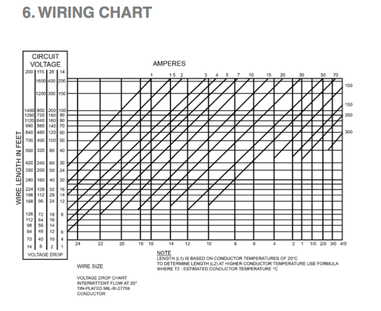
It was no simple task to get RG-400 coax cable for the GPS routed – and satisfactorily secured – on its way from the top-rear of the baggage area, down and then forward along the bottom of the rear fuselage to the center fuselage, and on to finally arrive behind the GTN 650Xi on the instrument panel. It’s done and it worked out very well.

Dealing with the COM 1 antenna coax cable was comparatively easier than for the GPS because the factory-supplied coax was already secured in place, routed from the mounting site on top of the rear fuselage, all the way to the instrument panel area. All I had to do was add the connectors.

The GPS antenna needed holes drilled in the fuselage skin. I used a doubler that came with my panel and harness and the screws provided with the Garmin GA 35 antenna. A TNC 90 degree solder/crimp connector by Amphenol made for a tidy connection at the top rear of the baggage compartment. A section of vinyl hose, covered with black heat shrink, provides good protection and satisfying aesthetics where the coax passes through the bulkhead, into the rear fuselage.

The COM 1 antenna needed 4 existing mounting holes to be expanded, in order to accept setting of rivnuts. The KAI called for M4 but the Rami antenna, supplied as part of my custom avionics package, came with 8-32 screws. I decided to set 8-32 rivnuts into the fuselage for this mounting. The way the coax was secured to the internal fuselage structure lent itself more to a 90 degree BNC connector. Again I selected an Amphenol solder/crimp part.

VS Structure, Antenna and Cables

Over a couple of sessions, I’ve installed additional m4 rivnuts, permanently riveted together the VS structure and mounted the VOR antenna base to Rib 004 – previously reinforced with its doubler.

Edge grommets have been applied to lightening holes of the rear channel and rib 003. I’ve elected to replace the factory-supplied rubber grommets with Heyco 0.375in nylon snap-bushings – to protect the coax and strobe light wiring where it passes through the VS structure. I enlarged the forming holes to 9.5mm, as directed. The forming holes at the front of ribs 002 and 003 were similarly enlarged to accommodate the bushings for my (optional, build-specific) VOR antenna coax cable. Routing the coax near the front of the structure is intended to keep the cable clear of the ‘works’ for the elevator.

After a bit of experimentation with my newly acquired rotary coax stripper, I installed the Amphenol BNC male connector to the RG-400 coax cable. As mentioned in a earlier post, I’ve decided to use M27500-20TG4T14 for the strobe – rather than the factory-supplied PVC jacketed wire. Some heat shrink tubing bulks up the cables as they pass through the bushings and the edge grommets. A few dollops of aluminum-compatable gasket-forming RTV locks down the bushings and the cables to the structure. I don’t want any movement from vibration.

VS Skin – Prep and Test Fit

I spent several work sessions to make sure I can expect good results when it comes time to close up the VS by riveting the skin to the underling structure. By that time – the VOR antenna, its RG-400 coax cable and the tail strobe wiring must be in place and will be expected to last the lifetime of the aircraft. No pressure!

Holes around the edges of the skin were typically large enough to accommodate 3,2 x 8mm domed rivets, but the holes in the skin at the interfaces with the ribs were smaller and needed to be enlarged with a #30 straight flute chucking reamer. All holes in the skin were carefully deburred. Overall, the concentric alignment of holes in skin and structure were pretty good, but a few will need to be match-reamed during the final fit, immediately prior to the riveting.

The antenna base required 4 recesses be machined into the plastic-like material that allow shortened rivets to fit without interference. My trusty Dremel Tool did both jobs handily – shortening the rivets and creating the recesses.

VOR Antenna Mount Fabrication

Incorporating a VOR antenna keeps my options open. The antenna gets built permanently into the VS structure. I have to commit to the antenna choice now, but not the avionics. The Rami AV-520 happens to be an ideal size and has removable whiskers. If I eventually decide that I don’t want or truly need VOR/LOC/GS capability, the whiskers come off and the VS of the bird is clean.

Optimum mounting the antenna requires a little custom fabrication. A doubler plate must be positioned and the mating rib drilled for rivets. I ordered the doubler base-plate part number from TAF. The top VS rib gets modification to accommodate the whiskers and provide access to set-screws.

The fabrication process I undertook was a variation of what is described in the Empennage Construction Manual, pp. VS4. Eventually, small holes also need to be located and created in the VS skin to accommodate the whiskers and tool access to the set-screws. Careful positioning of the antenna base allowed me to minimize impacts to the VS top rib and the skin.

Rivet clearance areas need to be machined into the (hard plastic-like) antenna base. Several rivets also need to be shortened. The general process for rivet shortening is in the construction manual. There are places where space is tight and a bit of finesse helps to achieve good fit.

Starting Off On the Right Foot

I ordered my quick-build kit in July and I’ve had my empennage sub-kit since August, but have yet to pull my first rivet. I’m finding that it’s taking many hours for research and for me to learn enough background information to make confident choices that will set the direction and metrics I will endeavor to satisfy as I build. I think that’s part of the fun.

Surface priming – materials and techniques – is a significant matter. I’m still wrangling a bit with that, but have determined that I have to be practical, or I’m never going to put pen to paper, so to speak. My priming standards are going to fall somewhere closer to the minimum of bare aluminum rather than the extraordinarily high level demonstrated by the truly awesome work of Pascal Latten for his Sling 2 build. Spray painting can be a messy and tedious business. I’m not a professional and I want to keep things clean and simple as possible, while achieving a worthwhile result. In a nutshell, I’m going to use RustOleum self-etching aerosol primer for most internal mating surfaces. For more exposed areas, such as the hinge areas and outward facing structure of the horizontal and vertical stabilizer assembies, I’ll use Alumiprep 33 and Alodine 1201, coated with more durable PTI 2 part epoxy primer – and ultimately the final color top coat.

Wiring, VOR antenna and external lighting choices figure in early for the empennage build.

Aveo Engineering produces what I think is the best option for the anti-collision light atop the rudder. For reasons that included fit, features and color, I’ve opted for the aviation red Posistrobe MiniMax to complement Aveo 3-in-1 nav/position/strobe lights on the wingtips – exact model number of the wingtip lights TBD. Without a huge amount of work, and or ready access to a completed Sling 2, it’s really mostly an educated guess that the overall lighting results will satisfy FAR 23.1385 – 23.1401. Hopefully it will and the DAR will agree.

Rudder Cap Strobe Mounting Area – small, even for the 1.74in wide MiniMax Light

Working through the electrical current requirements of the LED rudder strobe against AC 43.13B, I’ve tried to determine the necessary gauge and then acquire M27500 shielded cable to replace the TAF-supplied PVC jacketed wire in the kit. Based on actual experience with such wire in my Warrior, I’m not impressed with its suitability for aircraft applications. Based on my calculations, I think readily available 22 gauge conductors would be sufficient to handle peak current less than 3A over a run of 20ft. But, based on some data from the awesome builder I mentioned earlier, it’s possible that 20 gauge wire would be a better choice. I ordered some M27500-20TG4T14 from WireMasters. The minimum order was 100ft. This wire may turn out to be overkill for the small LED light. We’ll see.

You’ll find a chart like this in AC 43.13B

The VOR/GS antenna gets built into the vertical stabilizer, so I have to make a commitment to that, even before I’ve settled on my avionics choices. I’m hopeful that conformance with FAA TSO: C34e, C36e, C40c will make my choice compatible with whatever I finally choose for a VOR/GS receiver. Keeping the antenna price down will also make it easier to go with only a GPS navigator. At least the antenna and wiring will be in place. I’ve opted for the Rami AV-520 which has 2.5in diameter base “puck” with removable whips, built-in balun and coax connection.

I’m aiming for an advanced IFR all-Garmin EFIS panel with autopilot. We’ll see where it ends up.

I’ve ordered a bunch of stuff and it will be here next week. I’m perilously close to the official start my Sling 2 build.