
There’s lots of composite work to start and finish – and no shortage of details that need attention in the center and forward fuselage. It’s time to fit wheel fairings and prepare the compartment for the whole-aircraft ballistic parachute. The wingtips are getting closer. What a job those have been.
Category Archives: Firewall Forward
Under the Cowl – Work Goes On
With a bit of study and suitable periods of procrastination, I was able to rework the newer of the cabin heat shroud parts to fit the muffler. Knowledge and experience gleaned from my work with the heat valve duct was transferred to the outlet duct for the muffler shroud.
I got a start on the oil hoses and fittings. I’ve elected not to use any of the hose and a number of the fittings supplied with the FFW kit for the oil system. Rather than struggle with a vice to clamp fittings and attempting to push the hose onto the barbs – by hand – I picked up a Koul Tool. Not cheap, but it works ever so nicely – if, that is, your 90 and 45 degree fittings have a shoulder. Some of the FFW kit fittings don’t have a shoulder. I’ve replaced those with Aeroquip AQP AN8 fittings. I’ve also gone with matching high temp Aeroquip oil hose. All very nice stuff. Each hose I’m making has swivel fittings at both ends to make an entire system of modular components. Admittedly, I’ve deviated slightly from the plans and supplied parts here, but in a good way. I’m building as experimental in the USA, so I can tweak some things without a big hassle.
Now seemed like a good time to get the radiator and oil cooler secured to the lower cowl with the factory-supplied Sling 2-specific brackets. I’m using Camlocs instead of the kit-supplied Dzus fittings. They’re just better.
Cowl fitting continues, this time with a minimal cutout to clear the exhaust pipe. Eventually, I’ll be bonding reflective fiberglass heat shield to the inside of the cowling where needed.
Cowling and Muffler Work
Working with the fiberglass cowl halves just takes time. There have been many cycles of positioning the cowling, marking, removing the cowling, trimming or drilling. Rinse and repeat, as the saying goes. Figuring out how to compensate for a poorly made cabin heat muffler shroud is burning extra hours. Epoxy filler takes a really long time to cure. Who knew?
The basic size and shape of composite cowling, as it came from the factory, has some challenges. I attribute the issues to factory processes. I believe parts were removed from their molds before the epoxy was sufficiently cured. This resulted in some distortion around the edges that became firmly set into the parts. I’m having to work around that, and in some places, I’m actually going to need to correct the shape. More on that next month, I expect.
A significant amount of building up has been necessary. The material I’ve used is Polyfiber SuperFil. SuperFil is epoxy-based, not polyester. I avoid polyester fillers because I’ve observed deterioration over time. Time will tell how well SuperFil holds up. The batch of material I’ve acquired, when mixed, ends up being somewhat pasty and difficult to spread evenly. It takes all of 24 hours to set up, and in cold weather, considerably more time to fully cure. The time adds up. Days and weeks go by with not a great deal to show.
SuperFil is not exactly what I’d call fragile, but it’s not super tough either. It adheres well and sands well. I’ve tried to confine usage to places that don’t need to flex a great deal, as I think it might be somewhat vulnerable to cracking. In the future, I may try epoxy and microballoons. I don’t know if that will be any better, but I know it’s a popular and proven way to go.
As part of my firewall forward (FFW) kit, I received a new-style exhaust system, compared to what I’ve seen supplied for other Sling 2 builds. So far, I think that’s good. As sometimes happens with new parts, early production teething issues can creep in.
The cabin heat muffler shroud doesn’t fit. I noticed this early on and the factory sent me a new part (and part number), but it too doesn’t fit with the muffler. There are also some holes that should match at the overlap seam. They don’t. Obviously no QC standards were applied at all – I’m sorry to say. No excuse. (end rant) I could push for a yet another part from the factory, but don’t want to wear out my welcome any more than I have. At this point, I’m reasonably certain I can adapt one of the parts and build on.
I’ve learned – too late – that my choice of spinner was probably not a very good idea and that it brought me perilously close to a disaster that befell another Sling 2 builder who tried to use this same spinner. He had to buy a new cowl. I think I’m going to squeak by, but just barely. The setback necessary to accommodate the rear facing spinner bulkhead flange, competes with the available circumference at the rear edge of the cowl where it overlaps around the fuselage. Exhaust and engine clearances near the lower front of the cowl are also reduced, the farther back the cowl sits. At some point, luck runs out. I think perhaps the new-style exhaust may have saved me. The other builder had the old style. Nevertheless, I’ve come absolutely to the edge of a self-induced failure that would demand a new cowl. It’s very, very close.
I may still be in trouble with the cowl. The front lips of the upper and lower cowl haves have spacing and alignment issues that I’m working to correct with filler. The plane of the cowl ring formed at the front, nearest the spinner, is not the same as the face of the propeller hub. The engine mount introduces considerable right thrust and the cowling appear to have almost none. This results in an inconsistent gap on the left and right sides, just behind the spinner. When it’s all said and done, there’s going to be very little gap between the spinner and the cowl. I cannot set the cowl back any further. As it happens, I have a friend who designed and built an airplane 35 years ago with a similarly (and intentionally) small spinner to cowl gap and it has been absolutely fine. I think mine will be too. It’s sure going to look nice. Ultimately, time will tell if i get away with it.
Engine Cowling – Initial Trim and Fit
The composite engine cowling is one of the key contributors to the look of a Sling aircraft. I love the way Slings look. There are other models available from Sling Aircraft now, but it’s the Sling 2 that started it all. Now my Sling 2 is starting to look like it should.
There are a few pointers in the plans about the cowling, but mostly it’s up to the builder to figure out how to get the cowling to fit – properly and securely. I’ve complicated the process by introducing a custom spinner assembly. The factory-supplied spinner, while likely adequate, has to be built up from parts. The spinner I ordered through the propeller manufacturer – Whirlwind – is beautifully made from carbon fiber, comes finished and ready to paint. It’s a slightly different look, but still very, very Sling-like.
The 9.75″ Whirlwind spinner is notably different from the factory unit. The backing plate flange faces backward instead of forward. This will mean that the cowl will have to fit somewhat farther back on the fuselage than it otherwise would for the standard spinner.
To get the cowl aligned and with the proper setback, I’ve made a fixture that mounts to the prop hub extension. The hub extension is a standard part of the kit. Repeated fitting and trimming will hopefully arrive at a near perfect position and alignment. More to come on that.
Canopy Latch and Exhaust System
The canopy latch is inset within an oval area that must be carved out of the top front of the canopy plexiglass and underlying composite frame and held in place with blind M5 rivnuts and screws. Let’s just say that this is a challenging and nerve racking set of tasks. And – that’s a major understatement. But, with patience and a good bit of careful work with my trusty Dremel tool, I was able to achieve what I deem, at this point anyway, a satisfactory result.
The latch mechanism is an over-center affair with a hook engaging a latch pin that mounts to the top underside of windscreen support arch. Four 3,2 x 10mm CSK rivets attach the pin and it’s mounting plate to the arch, along with whatever additional security is afforded by a dollop of JB Weld epoxy. Where exactly to position the pin is an exercise left entirely to the discretion of the builder. Good luck with that.
I think by the time I get the weather seal in place, the latch will pull the canopy closed – firmly and without gaps. We’ll see. All of this latch fitment has happened before having the windscreen and support arch bonded in their forever positions. I’ve got my fingers crossed. Time will tell.
The exhaust system has been languishing in a box and it seemed a good time to see how well (if) it fits with the engine and airframe. It looks… maybe not so bad. Good!
There’s going to be some work needed to get the cabin heat muffler shroud assembled, because I don’t have a part that actually fits. So far, I’ve gotten 2 different parts (and part numbers) from the factory, but neither part matches the mounting rings on muffler. Argh. I’ll have to adapt and/or fabricate something. But, at least it seems the exhaust pipes and muffler do fit. Hooray for that.
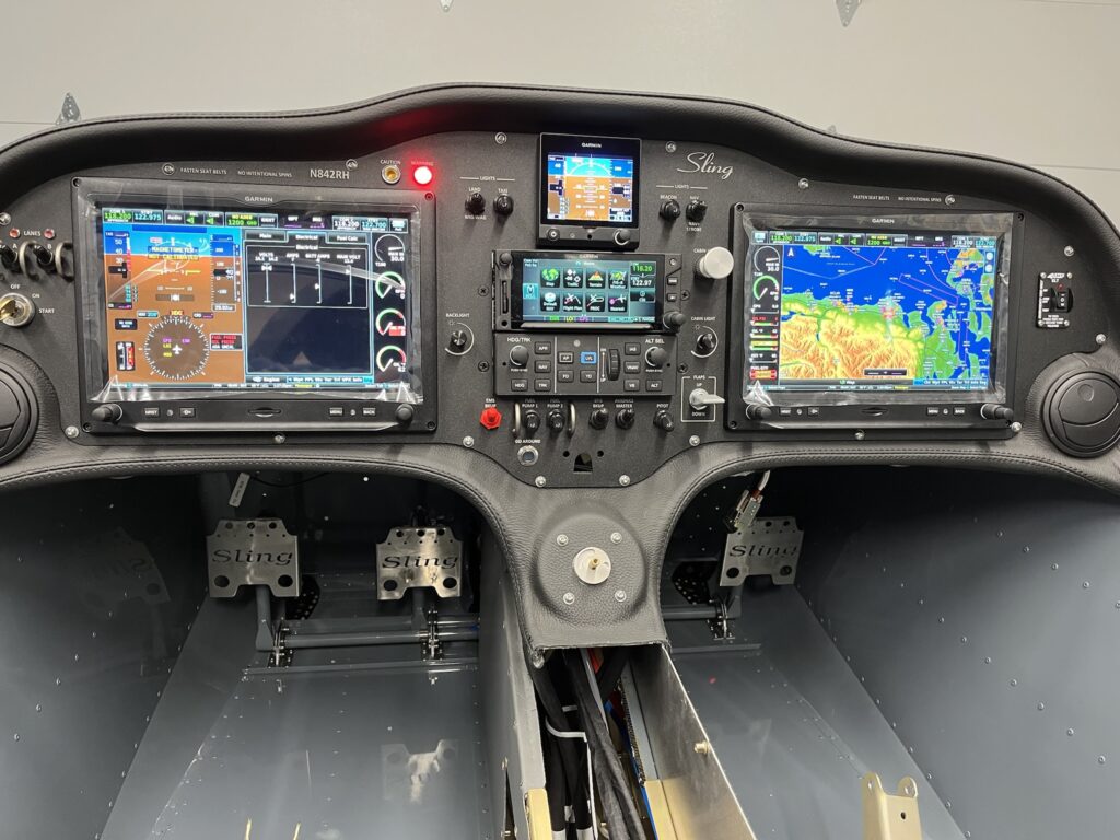
Glareshield/Dash and Instrument Panel
I’ve been working hard to finalize work behind the instrument panel before I permanently close up the area and bond the windscreen in place. Once that happens, any work behind the panel will have to be done though the openings where the GDU 460 displays go. I could possibly remove the whole panel from the dash, but it’s really and truly so nestled into place that I don’t want to disturb it. Disconnecting it, reconnecting it, pulling it out and fitting it back seems more challenging than I want to contemplate — or actually deal with. Get everything right before it all gets locked down – that’s the plan.
The fuselage top-skin on my factory QB came partially riveted in place. I removed it. I also dimpled the skin and the rib to accept 3,2 x 10mm countersunk rivets. The parachute compartment cover skins will eventually go over the countersunk rivets, to be held in place by just a few domed rivets and slotted “fingers” at the edges of the cover skins. I’ve put the top skin back into position with clecos. The dash has been positioned and match drilled with the skin to accept 3,2 x 8 mm domed rivets. The lip of the dash is bonded to the skin with very sticky double-sided tape – supplied with the kit. The next step is to pull the rivets on the lip of the dash.
Once the dash lip is riveted, it’ll be time to fit the windscreen. The windscreen has to transition from outside to inside. The dash does the same thing. The windscreen needs to go between the dash and the skin at the edges. It’s going to be tight. I probably won’t rivet the skin until, or even perhaps after, I do the bonding process for the windscreen with Sikaflex adhesive.
Before bonding, the windscreen and support arch must be fitted with the canopy. The windscreen will almost certainly need to be trimmed along the rear edge of the arch. It’s all going to be very delicate and require great care. If I crack or otherwise damage the plexiglass windscreen it would likely be many months before I could get another one.
At this point, I’ve managed to get the panel and dash positioned and connected to the harness. The wiring looks crazy. Ok, it is crazy. But, it’s pretty much the nature of the beast. This is a custom plug-n-play harness that’s essentially one piece. I laid it into the CF like a sleeping octopus. There’s extra craziness because of how much stuff I’ve got to connect. I think the only way to make it any neater would have required building the harness on the airplane. That just couldn’t happen. As it is, I’ve got all of the various “tentacles” dressed and secured about as naturally and as stress free as they can be. I’m very happy with it, even if it looks rather wild. There’s a lot there.
I’m delighted to report that once again, the panel has life. This time, the Engine Information System (EIS) is active. The sensors seem to be working. There are still things that aren’t connected yet. But for the things that are, it all looks great and my confidence is high.
So far, working the flap control, hearing the actuator run and seeing the indicator change is my favorite thing. The VP-X Pro and the G3X Touch integration seem nice. Working the radio frequencies and the remote audio panel is very cool. Both radios transmit and receive. The headset jacks are working, but I haven’t been able to try the LEMO connectors yet. Navigation, position and strobe lights work. Cabin lighting works. Oh so nice.
I’ve got to say, it’s more than just a little exciting. Build on!
FFW – Wiring and Fuel System Tasks
As I’ve mentioned before, the fuel system is just short of outrageous. It’s not bad. It’s just that there are plenty of bits and pieces to fit in awkward places, along with the ever present mandate of ensuring the robust integrity of every aspect of the system.
The Sling KAI provides guidance. Careful reading and understanding of the Rotax 912iS Installation Manual is a must. Let’s certainly not forget AC-43.13. All of the information lines up pretty well, yet there’s a lot left to the discretion of the builder.
I’m incorporating all of the fuel system features that appear in the KAI and the Rotax manual, with the exception of a fuel selector bypass check valve for the fuel return line. This valve appears in the Rotax fuel system schematic, but not in the KAI. The purpose of the check valve is to relieve pressure (of residual fuel in the system) to a fuel tank if one or both of the fuel pumps get turned on while the fuel selector is set to off. For now, I’m just going to be careful. But, after 20 years of maintenance experience with my Piper Warrior, I know that I’ve switched on the electric fuel pump [and started the engine] with the fuel turned off. Return pressure is not an issue for the Warrior, but the potential condition of fuel pump on and fuel selector off is common to both airplanes and I’ve already done it – more than once.
Also, as I’ve mentioned in other posts, I’m adding AN6 flare fittings in several places where only barbed fittings were provided with the kit. Key reasons for elimination of the barbs is to avoid awkward conditions for crimping the Oetiker ear clamps and to somewhat modularize sections of the fuel system. To my mind it seems advantageous to have separable pieces that can be unfastened and refastened with wrenches instead of having to cut and then crimp metal clamps. Adding bulkhead fittings for the supply and return lines pretty much demanded flare fittings. Being able to service/replace the fuel filter is another place where swivel fittings seem like they’d be somewhat more conventional and convenient.
The great majority of the fuel fittings are aluminum with just few brass NPT elbows at the fuel selector. Ahead of the firewall, steel fittings are often used, but for experimental applications anodized aluminum fitting are quite common, and as far a I know – not unacceptable. I’m not certain about the metal fuel lines themselves, but Piper put exclusively aluminum fuel fittings behind the firewall and in the wings of my ’84 Warrior II.
The kit provided a big fuel filter with barbs. The engine came with a Rotax part that pretty much everyone that’s building a Sling uses. Me to. The filter really needs to be secured in a suitable location. The sensible and popular location for the Sling 2 seems to be near the battery box. I designed and fabricated a bracket and clamp system.
Another consideration has to do with where to put the fuel pressure sender. Some builders have voiced concerns about making sure that the wet/pressure port faces down, to prevent pooling of fuel in the sender and orifice. I don’t know how big an issue that really is, but I found a place to put the sender and keep the port facing down. More AN6 fittings are involved. I designed and fabricated a bracket and attached the assembly to the engine mount with a cushioned clamp.
One of the things I’ve done is to upgrade the fuel hose. The kit provided SAE J30R7 hose for low pressure fuel supply and return lines. SAE J30R9 fuel injection hose was provided for the high pressure lines between the fuel pump an the engine. I’ve replaced all of the R7 hose with R9. The R9 hose has low permeability and resistance to methanol. There’s also R14 hose. It seems to be somewhat more available, but samples I’ve found are noticeably stiffer than R9 and I believe the pressure rating of the R14 is about half that of the R9. The R14 hose would probably be adequate, but I’ve gone exclusively with the R9.
I’ve built several of the short lines with connectors and firesleeve. I found push-lock fittings specifically for 5/16″ hose. Assembly with those fittings is easy. The ear clamps are solid.
The 5/16″ hose and and several of the fittings – especially the 1/8″ NPT fittings – are a bit on the narrow side. So franky are some of the barbed fittings supplied with the kit. I’m under the impression that the small variations I’ve made will not introduce inadequacies in the feeding of the miserly 912iS, even at full power. If it were a 914 or 915iS it would be a different story. From what I can see, I don’t think I’ve changed the game. I’ll test carefully, you can bet on that.
The fuel system also incorporates a tiny pressure relief channel between the supply and return lines that allow the high pressure side to bleed down into the return circuit when the [engine and] fuel pumps are turned off. Rotax shows this before the fuel filter, but the Sling 2 KAI shows it after. After lots of consideration, I think I’ll go with exactly how the KAI depicts it, using the T-fittings that were provided. I did however, purchase a clever manifold part from Lockwood Aviation that I’d seen on another builder’s blog. Since then I’ve seen the same part used on several Sling builds. The part incorporates the orifice for pressure relief, NPT threaded input and output fittings for pressure and return lines, and also a place to attach the fuel pressure sender, but all at the cost of more fittings that, in close proximity with the fuel filter and another check valve, presented an awkwardness that I don’t care for. I’ve decided not to use the Lockwood part.
Dealing with firewall penetrations is a subject with seemingly endless discussion. It’s a good topic, I’ll admit. The kit came with a big hole in the firewall and 2 halves of a cover plate. This is where avionics power and engine management cables go. The KAI makes a brief mention of the plate and setting some rivnuts, but not much more. I ended up making a sort of gland out of scrap silicone engine baffle material. My Warrior has the same thing where throttle and mixture cables penetrate the firewall. I replaced those cables some years ago. Piper used a paper-like material, but it had seen better days. The silicone material proved to be an excellent replacement for the Warrior. I’ve used the same material here. I’m not done with. It still needs to be sealed. But, it’s basically what I think I want.
While I’m working to get the FFW tasks finalized, my priority is getting the glare shield/dash, forward fuselage top-skin and windscreen done. I want the panel in final position and completely working before I do that. For confidence testing, I’m connecting up all of the power and grounds for the fusebox and engine.
Engine On
Bolting a factory new aircraft engine onto my own airplane is a dream come true. There’s so much going on it the world to be focused on this, but I am. I’m glad.
I’m also very glad to be amongst the extraordinary group of folks at EAA Chapter 430 – Olympic Peninsula. One of our chapter members so kindly shared his time and experience (and shop crane) to help me mount the new engine. Thanks Barry!!
Without further ado – a drum roll please…
Sling 2, N842RH (registration number reserved) — is today, powered by a Rotax 912iS Sport engine!
Wheels On
There’s not a whole lot to say except that the wheels are on!
The factory-supplied Matco wheels and brakes seem quite nice. I’d mounted the tubes and tires some time ago. I’ve packed the main wheel bearings with grease that came with the kit. The nose wheel has sealed bearings. I prepped the wheel fairing mounting brackets and treated them with alodine.
Jacking the airframe was a bit challenging. I’ll have to find a better way to do it for inspection and maintenance. Assembly went well.
It’s very good to see the thing up on its wheels.
FFW and CF Tasks
While the engine mount is off, I’m getting firewall forward and center fuselage tasks done that would be more challenging to do later.
I’m not keen about how the factory seems to expect the stiff-wire push-pull cable to go from the instrument panel, through the firewall and then to the heat box on the firewall. As with other firewall penetrations, I’m not content to just stuff the cable through the firewall with a grommet. I’m also not going to settle for having the cable penetrate the firewall at the absurd angle needed to even have a chance of getting to and working the heater box vane. Instead, I’ve designed and fabricated a jack-shaft bellcrank arrangement as an alternative. I’m still going to use the factory-supplied cable assembly – straight through the firewall, a bowden cable clamp and then attaching the wire to a nylon control horn. Another control horn, at the other end of a shaft, translates the push-pull control motion approximately 90 degrees – to be in line with the action needed to work the arm on the heater box vane. I made a couple of brackets out of aluminum angle and mounted the mechanism on the firewall.
Since my QB airframe was built and delivered, the factory has rethought how and where the ELT antenna goes – to just ahead of the vertical stabilizer. It’s too late for me. The structure was changed to accomodate a new mounting bracket and I’m not going to attempt a retrofit. The old location for the ELT antenna was inside the cabin. I’ve designed and fabricated a bracket to mount the antenna inside, just ahead of the rollover structure on the RH side of the fuselage.
Now that I’ve got my hands on the main battery – EarthX ETX 900, 16AH, LiFePo4 – I’ve been able to build and connect 4 AWG cables from the battery terminals to the 12V contactor and to the airframe ground lug. The high current cables are short and tidy.
I’ve had to acquire [standard AN] replacement hardware for re-mounting the engine mount, but this time, along with the front cables for the ballistic parachute. Longer bolts are needed to pass through the heavy cable-attachment tangs. Initially, I didn’t have the tangs. I eventually got those, along with a bunch of other factory parts that should have shipped with the main kit. The cables and the engine mount are on! Good deal.
With the engine mount in place, I’ve mounted the nose gear strut. Some months ago I accomplished fitting of the bushings, retainers and bolts. That made is super easy to just bolt it all together and connect the push-pull rods to the rudder pedals linkage.
I’m still waiting to put the wheels on because the fuselage is that much lower to the ground, making the inside of the center fuselage (CF) somewhat more accessible than it would be with it higher. I’m taking advantage of the easier access while I dress and secure the wiring and prepare parts of the control linkages and autopilot roll servo.
I’m pretty happy with my approach to securing wire harness bundles as they pass through various openings in the CF structure. I found a source for AN743-13 aluminum angle brackets. These brackets are just right for supporting insulated (Adel) clamps around the wire bundles. It was very challenging to drill holes and rivet the brackets at this late stage of the build. I didn’t have the luxury of doing it while the structure was open, sitting on the bench. Nevertheless, the brackets and clamps are in place and they’re pretty nice. I’ve also put some edge grommet in a few places, just for peace of mind.
I’ve previously tested the flap actuator with temporary connections, but now I’ve made the connections permanent with crimped butt-connectors and various layers of insulation and protective armoring. I’ve done checks to insure that the wiring will be clear of moving mechanisms. It all looks very promising and I’m feeling happy about the work.
Another thing I’m pretty happy about was my purchase of a simple jig for drilling nice cross-holes in the control tubes. Beautiful!