With a bit of study and suitable periods of procrastination, I was able to rework the newer of the cabin heat shroud parts to fit the muffler. Knowledge and experience gleaned from my work with the heat valve duct was transferred to the outlet duct for the muffler shroud.
I got a start on the oil hoses and fittings. I’ve elected not to use any of the hose and a number of the fittings supplied with the FFW kit for the oil system. Rather than struggle with a vice to clamp fittings and attempting to push the hose onto the barbs – by hand – I picked up a Koul Tool. Not cheap, but it works ever so nicely – if, that is, your 90 and 45 degree fittings have a shoulder. Some of the FFW kit fittings don’t have a shoulder. I’ve replaced those with Aeroquip AQP AN8 fittings. I’ve also gone with matching high temp Aeroquip oil hose. All very nice stuff. Each hose I’m making has swivel fittings at both ends to make an entire system of modular components. Admittedly, I’ve deviated slightly from the plans and supplied parts here, but in a good way. I’m building as experimental in the USA, so I can tweak some things without a big hassle.
Now seemed like a good time to get the radiator and oil cooler secured to the lower cowl with the factory-supplied Sling 2-specific brackets. I’m using Camlocs instead of the kit-supplied Dzus fittings. They’re just better.
Cowl fitting continues, this time with a minimal cutout to clear the exhaust pipe. Eventually, I’ll be bonding reflective fiberglass heat shield to the inside of the cowling where needed.
Working with the fiberglass cowl halves just takes time. There have been many cycles of positioning the cowling, marking, removing the cowling, trimming or drilling. Rinse and repeat, as the saying goes. Figuring out how to compensate for a poorly made cabin heat muffler shroud is burning extra hours. Epoxy filler takes a really long time to cure. Who knew?
The basic size and shape of composite cowling, as it came from the factory, has some challenges. I attribute the issues to factory processes. I believe parts were removed from their molds before the epoxy was sufficiently cured. This resulted in some distortion around the edges that became firmly set into the parts. I’m having to work around that, and in some places, I’m actually going to need to correct the shape. More on that next month, I expect.
A significant amount of building up has been necessary. The material I’ve used is Polyfiber SuperFil. SuperFil is epoxy-based, not polyester. I avoid polyester fillers because I’ve observed deterioration over time. Time will tell how well SuperFil holds up. The batch of material I’ve acquired, when mixed, ends up being somewhat pasty and difficult to spread evenly. It takes all of 24 hours to set up, and in cold weather, considerably more time to fully cure. The time adds up. Days and weeks go by with not a great deal to show.
SuperFil is not exactly what I’d call fragile, but it’s not super tough either. It adheres well and sands well. I’ve tried to confine usage to places that don’t need to flex a great deal, as I think it might be somewhat vulnerable to cracking. In the future, I may try epoxy and microballoons. I don’t know if that will be any better, but I know it’s a popular and proven way to go.
As part of my firewall forward (FFW) kit, I received a new-style exhaust system, compared to what I’ve seen supplied for other Sling 2 builds. So far, I think that’s good. As sometimes happens with new parts, early production teething issues can creep in.
The cabin heat muffler shroud doesn’t fit. I noticed this early on and the factory sent me a new part (and part number), but it too doesn’t fit with the muffler. There are also some holes that should match at the overlap seam. They don’t. Obviously no QC standards were applied at all – I’m sorry to say. No excuse. (end rant) I could push for a yet another part from the factory, but don’t want to wear out my welcome any more than I have. At this point, I’m reasonably certain I can adapt one of the parts and build on.
I’ve learned – too late – that my choice of spinner was probably not a very good idea and that it brought me perilously close to a disaster that befell another Sling 2 builder who tried to use this same spinner. He had to buy a new cowl. I think I’m going to squeak by, but just barely. The setback necessary to accommodate the rear facing spinner bulkhead flange, competes with the available circumference at the rear edge of the cowl where it overlaps around the fuselage. Exhaust and engine clearances near the lower front of the cowl are also reduced, the farther back the cowl sits. At some point, luck runs out. I think perhaps the new-style exhaust may have saved me. The other builder had the old style. Nevertheless, I’ve come absolutely to the edge of a self-induced failure that would demand a new cowl. It’s very, very close.
I may still be in trouble with the cowl. The front lips of the upper and lower cowl haves have spacing and alignment issues that I’m working to correct with filler. The plane of the cowl ring formed at the front, nearest the spinner, is not the same as the face of the propeller hub. The engine mount introduces considerable right thrust and the cowling appear to have almost none. This results in an inconsistent gap on the left and right sides, just behind the spinner. When it’s all said and done, there’s going to be very little gap between the spinner and the cowl. I cannot set the cowl back any further. As it happens, I have a friend who designed and built an airplane 35 years ago with a similarly (and intentionally) small spinner to cowl gap and it has been absolutely fine. I think mine will be too. It’s sure going to look nice. Ultimately, time will tell if i get away with it.
Having put this off as long as I could, I’ve summoned the courage to trim the windscreen until it fits. I absolutely do not want to crack it and I cannot afford to over-trim. It has to be done, just so. If ever there was a time to apply, measure twice, cut once – this is it!
Along the way, I take comfort in and from small stress-reducing distractions. Testing out my fancy new lithium battery charger yields a few moments to gather myself. The charger has a feature that can supply up to 10A of current to power the avionics and allow for extended sessions of testing, configuration and familiarization – ok, play! There’s a lot to learn and it’s going to take quite a bit of play time.
Rivets, wires and avionics are friendly territory for me, compared to where I’m headed now. Fitting the windscreen and getting it bonded in position are tasks I’ve been apprehensive about – extremely apprehensive.
Manipulating clear acrylic sheet – Plexiglass and Perspex are brand names – that’s been molded into compound curves of unusual size, is just asking for trouble. I don’t like trouble. Dealing with this stuff is tricky, all by itself. Don’t even get me started about cutting or drilling holes in it. Eventually, I’m going to add sticky gooey pitch black marine adhesive caulk to the mix. That could easily lead to – yes, you guessed it – super trouble!
The time has come. I can’t avoid it any longer.
Because I opted for a factory quick-build kit, it came with the main canopy already trimmed and bonded to its painted composite frame. That’s fortunate because it may well have spared my frazzled nerves just enough to be able to deal with the windscreen.
The initial canopy placement seemed easy enough. Screw holes in the frame aligned with the ones in the slide assemblies. Countersinking of the frame will be needed to correspond with the short M8 stainless steel CSK mounting screws.
The arched windscreen support frame was fitted and match-drilled to align with M5 rivnuts that were installed at the factory. I made cardboard templates for left and right sides because they’re different. (They shouldn’t be – but that’s how the factory built it.)
The trial fit reveals that the rear edge of the windscreen will have to be cut back by at least 4 or 5 cm to align with the arched support frame. The lower rear edges (corners) of the plexiglass will just barely be under the fuselage top skin when it’s riveted in place. Precise positioning of the windscreen is going to be extremely important to avoid any unsightly gaps between the aluminum skin and the plexiglass.
A latch mechanism has to be fitted into the canopy. I inventoried the latch parts when I received them, but I could not have detected that the supplied spring was not correctly formed. I checked with the factory and confirmed the situation. They’re going to send me a replacement spring.
Windscreen cutting, drilling and bonding comes next.
I’ve been working hard to finalize work behind the instrument panel before I permanently close up the area and bond the windscreen in place. Once that happens, any work behind the panel will have to be done though the openings where the GDU 460 displays go. I could possibly remove the whole panel from the dash, but it’s really and truly so nestled into place that I don’t want to disturb it. Disconnecting it, reconnecting it, pulling it out and fitting it back seems more challenging than I want to contemplate — or actually deal with. Get everything right before it all gets locked down – that’s the plan.
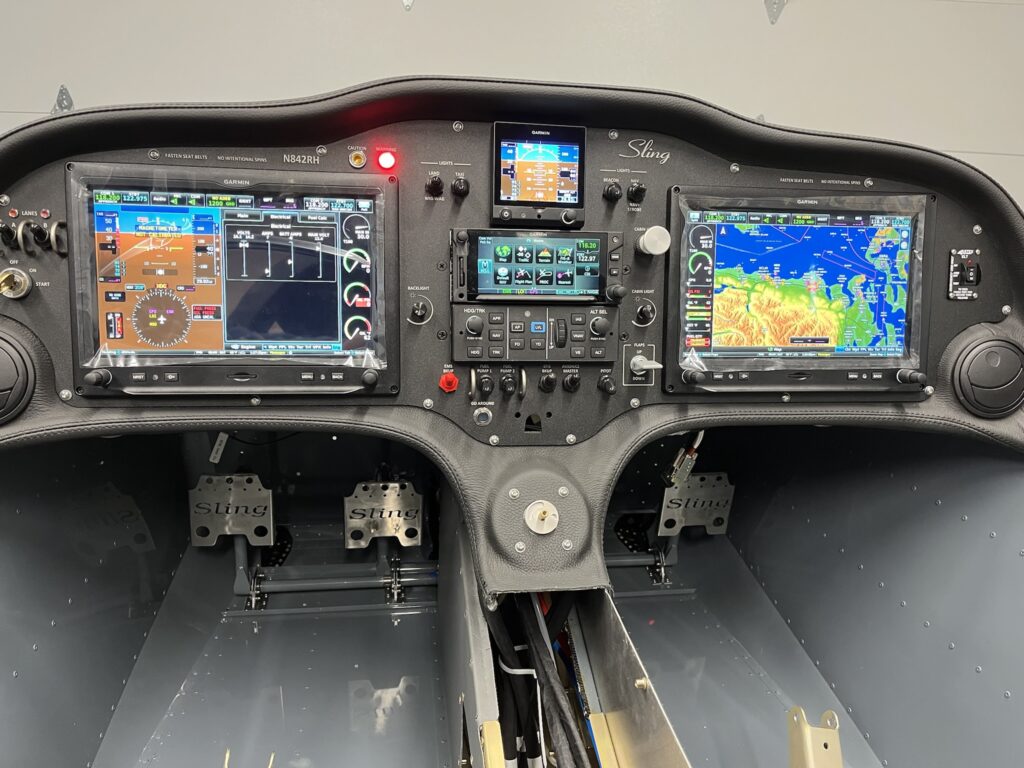
Instrument Panel Powered Up with Engine Information System (EIS) Displayed
The fuselage top-skin on my factory QB came partially riveted in place. I removed it. I also dimpled the skin and the rib to accept 3,2 x 10mm countersunk rivets. The parachute compartment cover skins will eventually go over the countersunk rivets, to be held in place by just a few domed rivets and slotted “fingers” at the edges of the cover skins. I’ve put the top skin back into position with clecos. The dash has been positioned and match drilled with the skin to accept 3,2 x 8 mm domed rivets. The lip of the dash is bonded to the skin with very sticky double-sided tape – supplied with the kit. The next step is to pull the rivets on the lip of the dash.
Once the dash lip is riveted, it’ll be time to fit the windscreen. The windscreen has to transition from outside to inside. The dash does the same thing. The windscreen needs to go between the dash and the skin at the edges. It’s going to be tight. I probably won’t rivet the skin until, or even perhaps after, I do the bonding process for the windscreen with Sikaflex adhesive.
Before bonding, the windscreen and support arch must be fitted with the canopy. The windscreen will almost certainly need to be trimmed along the rear edge of the arch. It’s all going to be very delicate and require great care. If I crack or otherwise damage the plexiglass windscreen it would likely be many months before I could get another one.
At this point, I’ve managed to get the panel and dash positioned and connected to the harness. The wiring looks crazy. Ok, it is crazy. But, it’s pretty much the nature of the beast. This is a custom plug-n-play harness that’s essentially one piece. I laid it into the CF like a sleeping octopus. There’s extra craziness because of how much stuff I’ve got to connect. I think the only way to make it any neater would have required building the harness on the airplane. That just couldn’t happen. As it is, I’ve got all of the various “tentacles” dressed and secured about as naturally and as stress free as they can be. I’m very happy with it, even if it looks rather wild. There’s a lot there.
I’m delighted to report that once again, the panel has life. This time, the Engine Information System (EIS) is active. The sensors seem to be working. There are still things that aren’t connected yet. But for the things that are, it all looks great and my confidence is high.
So far, working the flap control, hearing the actuator run and seeing the indicator change is my favorite thing. The VP-X Pro and the G3X Touch integration seem nice. Working the radio frequencies and the remote audio panel is very cool. Both radios transmit and receive. The headset jacks are working, but I haven’t been able to try the LEMO connectors yet. Navigation, position and strobe lights work. Cabin lighting works. Oh so nice.
I’ve got to say, it’s more than just a little exciting. Build on!
Upholstery work takes a bit of courage and determination – at least for me it does. A big part of the work involves trimming the vinyl leatherette-like covering to fit the center console and then bonding pieces of material to some rather sizable and awkwardly shaped panels – everything is frighteningly sticky with spray adhesive.
I got through it and it all seems to look rather nice. I can’t say I’d do it the same way again, but at the same time, I don’t exactly know what I’d have done differently. You’ve just got to do the best you can.
All of the center upholstery pieces came in a kit, along with fiberglass-backed side panels, seat and seat back cushions, and carpet panels for the floor and luggage compartment. The seats cushions are covered with genuine leather and stitched by professionals. I got to choose the colors. Methinks it’s going to be a rather sporty and plush setup for this little 2-seater. Oh well! What can I say?
Once the rear portion of the center console was covered, it seemed a good time to put it into position. The inside seatbelts pass through, so it was time to assemble those to their anchors. I haven’t riveted the rear console yet – just clecos for now.
The front console panels have 3 sections. The top panel of the LH side is removable for inspections, as are 4 other square panels – 2 of which are covered with the vinyl. The 2 forward most panels are painted, along with 2 panels for the baggage area.
Bonding the covering to the RH side panel was the biggest challenge. The section of material was large enough to be unwieldy. Working conditions inside the CF were awkward. I did, however, manage to lay in the material and get it satisfactorily positioned. I’m happy to have that task in my rearview mirror.
This seemed a good time to complete more of the wire connections to the rear fuselage (RF) section for the tail beacon and electric pitch trim servo. The PVC jacketed wires in the RF were routed and secured as part of the factory quick-build (QB). My custom avionics harness was provided with “pigtail” connectors. I connected the wires of the pigtail to the fuselage wires with Raychem D-436 series butt splice connectors. The connectors are a bit expensive and a special crimp tool is required. I believe the resulting connections are more than satisfactory. As usual, I insulate and protect the connections and secure them from movement.
While the engine mount is off, I’m getting firewall forward and center fuselage tasks done that would be more challenging to do later.
I’m not keen about how the factory seems to expect the stiff-wire push-pull cable to go from the instrument panel, through the firewall and then to the heat box on the firewall. As with other firewall penetrations, I’m not content to just stuff the cable through the firewall with a grommet. I’m also not going to settle for having the cable penetrate the firewall at the absurd angle needed to even have a chance of getting to and working the heater box vane. Instead, I’ve designed and fabricated a jack-shaft bellcrank arrangement as an alternative. I’m still going to use the factory-supplied cable assembly – straight through the firewall, a bowden cable clamp and then attaching the wire to a nylon control horn. Another control horn, at the other end of a shaft, translates the push-pull control motion approximately 90 degrees – to be in line with the action needed to work the arm on the heater box vane. I made a couple of brackets out of aluminum angle and mounted the mechanism on the firewall.
Since my QB airframe was built and delivered, the factory has rethought how and where the ELT antenna goes – to just ahead of the vertical stabilizer. It’s too late for me. The structure was changed to accomodate a new mounting bracket and I’m not going to attempt a retrofit. The old location for the ELT antenna was inside the cabin. I’ve designed and fabricated a bracket to mount the antenna inside, just ahead of the rollover structure on the RH side of the fuselage.
Now that I’ve got my hands on the main battery – EarthX ETX 900, 16AH, LiFePo4 – I’ve been able to build and connect 4 AWG cables from the battery terminals to the 12V contactor and to the airframe ground lug. The high current cables are short and tidy.
I’ve had to acquire [standard AN] replacement hardware for re-mounting the engine mount, but this time, along with the front cables for the ballistic parachute. Longer bolts are needed to pass through the heavy cable-attachment tangs. Initially, I didn’t have the tangs. I eventually got those, along with a bunch of other factory parts that should have shipped with the main kit. The cables and the engine mount are on! Good deal.
With the engine mount in place, I’ve mounted the nose gear strut. Some months ago I accomplished fitting of the bushings, retainers and bolts. That made is super easy to just bolt it all together and connect the push-pull rods to the rudder pedals linkage.
I’m still waiting to put the wheels on because the fuselage is that much lower to the ground, making the inside of the center fuselage (CF) somewhat more accessible than it would be with it higher. I’m taking advantage of the easier access while I dress and secure the wiring and prepare parts of the control linkages and autopilot roll servo.
I’m pretty happy with my approach to securing wire harness bundles as they pass through various openings in the CF structure. I found a source for AN743-13 aluminum angle brackets. These brackets are just right for supporting insulated (Adel) clamps around the wire bundles. It was very challenging to drill holes and rivet the brackets at this late stage of the build. I didn’t have the luxury of doing it while the structure was open, sitting on the bench. Nevertheless, the brackets and clamps are in place and they’re pretty nice. I’ve also put some edge grommet in a few places, just for peace of mind.
I’ve previously tested the flap actuator with temporary connections, but now I’ve made the connections permanent with crimped butt-connectors and various layers of insulation and protective armoring. I’ve done checks to insure that the wiring will be clear of moving mechanisms. It all looks very promising and I’m feeling happy about the work.
Another thing I’m pretty happy about was my purchase of a simple jig for drilling nice cross-holes in the control tubes. Beautiful!
The navigation avionics and engine management systems each have a TCW Integrated Battery Backup System (IBBS). The backup systems provide essential power in the event that one or both alternators in the Rotax 912iS engine should fail. There are 2 battery power units that have to be mounted someplace. I’ve found a spot on the fuselage rib, behind the parachute compartment that is within comfortable reach of the associated wiring harness connectors.
I thought that the batteries could use more support than they would get, were they attached directly to the rib. I designed and fabricated doubler plates to reinforce the rib. The batteries are fastened to the doublers.
I’ve had to consider that one day the battery units will have to be replaced. It won’t be easy, but I will be able to get to them from the front, after I remove the pilot side display and the remote LRUs and vertical rack that sit behind it.
Most of the remotely mounted avionics will be behind the instrument panel, on a custom designed and fabricated rack. Each Line Replaceable Unit (LRU) has a specific position on the rack and the harness is custom tailored to precisely reach and connect all of the units together, along with all of the other electrical systems in the aircraft.
I elected to have the harness and panel professionally designed and fabricated by Midwest Panel Builders in Lapeer, Michigan — specifically for my Sling 2 and its extensive Garmin G3X advanced IFR avionics suite. While I might have been able to manage the panel and wiring for a modest VFR setup, there was no way I was going to attempt it for this project.
Even with the custom-made harness, rack and panel there is still plenty of fitting and integration for me to do. This is no paint-by-numbers ELSA project. It’s full-on experimental amateur-built — all the way. I can’t wait to begin training for my IFR rating in this aircraft.
The LRU rack is a replacement for the one I received back in April. The original rack was the first of an all new design and needed several refinements.
The new rack needed to be fitted and the mounting points established. The center portion of the rack needed support. I designed and fabricated a bracket. Everything fits nicely.
After a gallant effort on the original RH wingtip, I ordered and received a replacement RH wingtip. The new part still had too much length and thickness at the trailing edge, but the workmanship of the layup was much improved and it had noticeably better overall shape. It has still taken lots of work to get the new RH tip to fit. But, it’s coming along and it’s going to work out well.
The LH tip is proving to be huge headache. Despite extensive rework, it’s now clear that the LH wingtip isn’t close enough to the proper cross section to fit and it would take extraordinary effort to get it in the ballpark.
Just like the RH wingtip, the length of the LH part at trailing edge is too long and the trailing edge profile (taper) is too thick to fit the trailing edge wing skin. But the kicker is the overall height. It’s just too narrow – top to bottom. It’s almost 2 cm short, at the widest point.
Trying to stretch the height of the LH tip requires too much force. The LH wingtip has no imbedded reinforcement strip on the bottom edge. The top reinforcement is out of position. Without proper stiffness, the tendency for waviness between the rivet holes would be profound.
To continue with the original LH wingtip, I’d have to section the part and almost re-manufacture it. I’ve decided that it’s much too much time and effort, although I have seen one other builder go to such lengths and spent over 130 hours on just trying to get his wingtips to fit. I’m at more than 40 hours on wingtips and I’m going to cut my losses and get a better baseline part.
I went ahead and negotiated a new LH wingtip from the factory, as I did for the RH side. They’ve kindly agreed to send me one. Kudos to Sling Aircraft for standing by their product. Stay tuned.