With a bit of study and suitable periods of procrastination, I was able to rework the newer of the cabin heat shroud parts to fit the muffler. Knowledge and experience gleaned from my work with the heat valve duct was transferred to the outlet duct for the muffler shroud.
I got a start on the oil hoses and fittings. I’ve elected not to use any of the hose and a number of the fittings supplied with the FFW kit for the oil system. Rather than struggle with a vice to clamp fittings and attempting to push the hose onto the barbs – by hand – I picked up a Koul Tool. Not cheap, but it works ever so nicely – if, that is, your 90 and 45 degree fittings have a shoulder. Some of the FFW kit fittings don’t have a shoulder. I’ve replaced those with Aeroquip AQP AN8 fittings. I’ve also gone with matching high temp Aeroquip oil hose. All very nice stuff. Each hose I’m making has swivel fittings at both ends to make an entire system of modular components. Admittedly, I’ve deviated slightly from the plans and supplied parts here, but in a good way. I’m building as experimental in the USA, so I can tweak some things without a big hassle.
Now seemed like a good time to get the radiator and oil cooler secured to the lower cowl with the factory-supplied Sling 2-specific brackets. I’m using Camlocs instead of the kit-supplied Dzus fittings. They’re just better.
Cowl fitting continues, this time with a minimal cutout to clear the exhaust pipe. Eventually, I’ll be bonding reflective fiberglass heat shield to the inside of the cowling where needed.
I’ve been working hard to finalize work behind the instrument panel before I permanently close up the area and bond the windscreen in place. Once that happens, any work behind the panel will have to be done though the openings where the GDU 460 displays go. I could possibly remove the whole panel from the dash, but it’s really and truly so nestled into place that I don’t want to disturb it. Disconnecting it, reconnecting it, pulling it out and fitting it back seems more challenging than I want to contemplate — or actually deal with. Get everything right before it all gets locked down – that’s the plan.
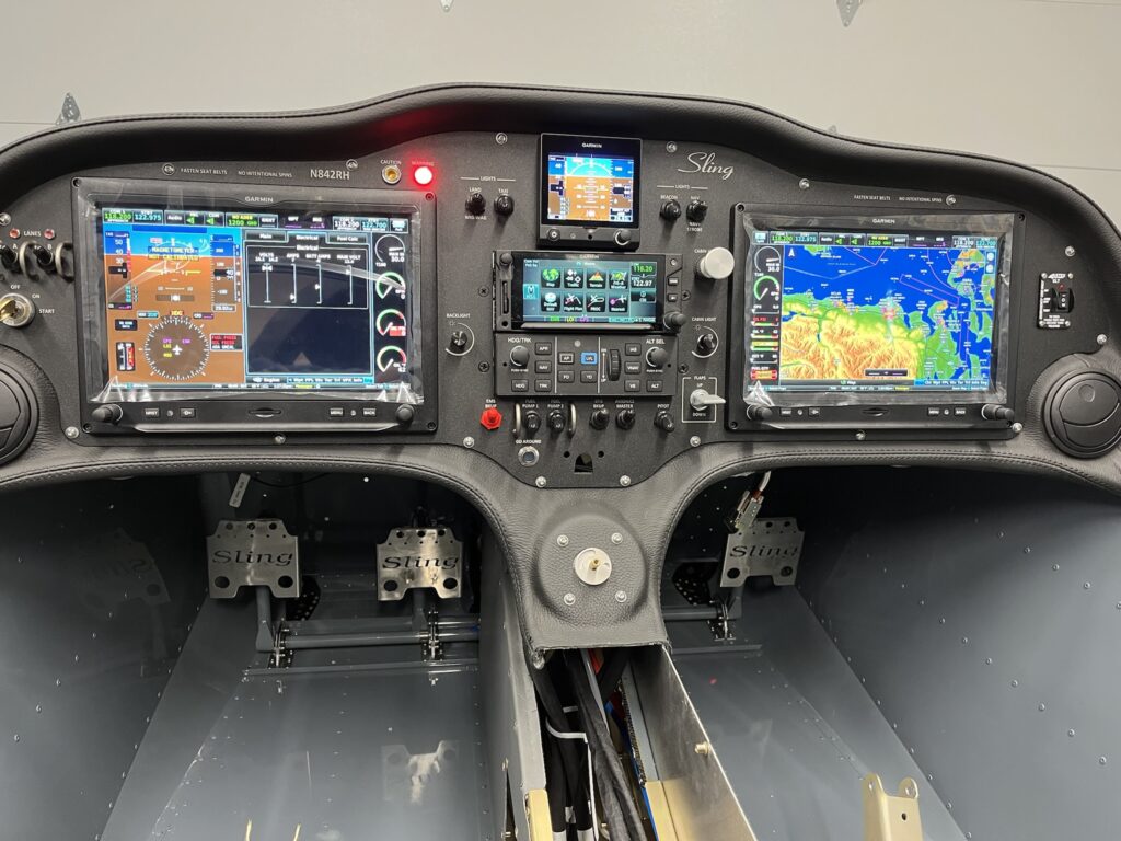
Instrument Panel Powered Up with Engine Information System (EIS) Displayed
The fuselage top-skin on my factory QB came partially riveted in place. I removed it. I also dimpled the skin and the rib to accept 3,2 x 10mm countersunk rivets. The parachute compartment cover skins will eventually go over the countersunk rivets, to be held in place by just a few domed rivets and slotted “fingers” at the edges of the cover skins. I’ve put the top skin back into position with clecos. The dash has been positioned and match drilled with the skin to accept 3,2 x 8 mm domed rivets. The lip of the dash is bonded to the skin with very sticky double-sided tape – supplied with the kit. The next step is to pull the rivets on the lip of the dash.
Once the dash lip is riveted, it’ll be time to fit the windscreen. The windscreen has to transition from outside to inside. The dash does the same thing. The windscreen needs to go between the dash and the skin at the edges. It’s going to be tight. I probably won’t rivet the skin until, or even perhaps after, I do the bonding process for the windscreen with Sikaflex adhesive.
Before bonding, the windscreen and support arch must be fitted with the canopy. The windscreen will almost certainly need to be trimmed along the rear edge of the arch. It’s all going to be very delicate and require great care. If I crack or otherwise damage the plexiglass windscreen it would likely be many months before I could get another one.
At this point, I’ve managed to get the panel and dash positioned and connected to the harness. The wiring looks crazy. Ok, it is crazy. But, it’s pretty much the nature of the beast. This is a custom plug-n-play harness that’s essentially one piece. I laid it into the CF like a sleeping octopus. There’s extra craziness because of how much stuff I’ve got to connect. I think the only way to make it any neater would have required building the harness on the airplane. That just couldn’t happen. As it is, I’ve got all of the various “tentacles” dressed and secured about as naturally and as stress free as they can be. I’m very happy with it, even if it looks rather wild. There’s a lot there.
I’m delighted to report that once again, the panel has life. This time, the Engine Information System (EIS) is active. The sensors seem to be working. There are still things that aren’t connected yet. But for the things that are, it all looks great and my confidence is high.
So far, working the flap control, hearing the actuator run and seeing the indicator change is my favorite thing. The VP-X Pro and the G3X Touch integration seem nice. Working the radio frequencies and the remote audio panel is very cool. Both radios transmit and receive. The headset jacks are working, but I haven’t been able to try the LEMO connectors yet. Navigation, position and strobe lights work. Cabin lighting works. Oh so nice.
I’ve got to say, it’s more than just a little exciting. Build on!
For an E/A-B project there’s a seemingly endless list of small tasks. Some things are simply items in the KAI. Other tasks are things that come to mind as you think about how its all going to come together. Task creep just seems to happen. As long as it doesn’t get out of hand – it’s a good thing.
There is a daunting amount of wiring to support the avionics I’ve elected to squeeze into this airplane. Frankly, I’ve gone overboard. On the other hand, I’ve got all of the makings for a technologically advanced airplane (TAA), extremely well equipped for IFR training and cross-country adventuring. Finding good ways to dress and secure the wiring bundles is important. I’ve put a lot of thought into it and determined that an extra bracket will help me keep the harness up and out of the way. I designed and fabricated one.
Many things have to be squeezed into available space without undue conflict. Wiring, fuel lines, pneumatic lines, brake lines, valves, linkages and such. While there are plenty of best practices for how to do things in airplanes, finding ways to apply them to all of the situations that present themselves is what keeps this amateur builder scrambling for ideas. There’s always something new to learn. It’s fun. Challenging, but fun. Yes. It is. I think.
The fuel-injected Rotax engine has a somewhat complex fuel system. The fuel lines have a fuel supply circuit and a fuel return circuit. When you add filters and a duplex fuel selector and physical considerations, the plumbing details border on outrageous. How I do it is up to me. The KAI supplies only general information. I’m also introducing AN6 flare and push-lock swivel fittings in several places where barbs and ear clamps were originally called out and supplied. Figuring out where and how to mount and connect many of the fuel system components is ongoing.
Some tasks just need doing. Then they’re done. Cutting coax cables to length and adding connectors is straightforward enough. Done. The Rotax 30A Regulator B needs a heat sink that calls for the regulator to move from the fusebox to a nearby location on the engine mount. Done. There are a couple of GPS antennas for the PFD and G5 flight instrument that found homes on top of the GAD 29, above the center avionics stack.
Brake lines need to be routed. The time to do it was now. One line goes from the brake fluid reservoir, through the firewall, to just under where the throttle and brake quadrant is located. From there, another line originates at the pressure side of the master brake cylinder an runs to a compression T-fitting under the console compartment. Two other lines run from the T-fitting, down the main gear legs to each wheel. The combination of the 3 lines and the T-fitting were challenging to place. I should have done it earlier, when access was better. It’s done now.
I received some [evidently] old-style mounting hardware for the parachute activation handle, so I ended making a small bracket to secure the activation pull-handle to the back of the instrument panel. It’s nice. It’s done. My design turned out to be a slightly improved version of a bracket I eventually saw in a photo from the factory. Great minds think alike.
It was time for pneumatic lines to go in. I found a really nice way to route them from the left wing root, though the center console and up behind the instrument panel. Because I’ve seen that the Sling TSi documentation now shows 2 static ports, I added a second one in front of the LH fresh air NACA duct. Both of the equal length static port lines arrive at a push-to-connect T-fitting at the center console. A short line runs from the first tee to another T-fitting that provides two more equal length lines to the the G5 and to the GSU 25C ADAHRS unit. The pitot line has a single T-fitting that also splits between G5 and the GSU 25. The AOA line only goes to the GSU 25. All done.
Most of the remotely mounted avionics will be behind the instrument panel, on a custom designed and fabricated rack. Each Line Replaceable Unit (LRU) has a specific position on the rack and the harness is custom tailored to precisely reach and connect all of the units together, along with all of the other electrical systems in the aircraft.
I elected to have the harness and panel professionally designed and fabricated by Midwest Panel Builders in Lapeer, Michigan — specifically for my Sling 2 and its extensive Garmin G3X advanced IFR avionics suite. While I might have been able to manage the panel and wiring for a modest VFR setup, there was no way I was going to attempt it for this project.
Even with the custom-made harness, rack and panel there is still plenty of fitting and integration for me to do. This is no paint-by-numbers ELSA project. It’s full-on experimental amateur-built — all the way. I can’t wait to begin training for my IFR rating in this aircraft.
The LRU rack is a replacement for the one I received back in April. The original rack was the first of an all new design and needed several refinements.
The new rack needed to be fitted and the mounting points established. The center portion of the rack needed support. I designed and fabricated a bracket. Everything fits nicely.
The fiberglass composite wingtips are needing a lot of rework. I don’t really believe it was intended be this way. What’s a simple amateur home-builder supposed to think?
The biggest area needing attention seems to be where the inside trailing edge of the wingtip is supposed to fit into the narrow skin at the tip of the wing. Several issues are being dealt with. Overall length is too long – by about 2cm (almost 1/2 inch). And, the fiberglass structure doesn’t match the contour of the wing profile near the TE. The taper of the fiberglass needs to become quite narrow. Plus – it’s all got to look pleasing and with and both wingtips ending up to be nicely matched – both aesthetically and aerodynamically.
I’ve decided that some sort of struts are needed to help the wingtips fit the contour of the wing. The kit instructions indicate that the wingtips are just match drilled and riveted. But, just letting the rivets pull the fiberglass shape seems like it’s going to lead to unwanted waviness from dips between the rivets. I fabricated simple struts to take some of the tension load off of the rivets. We’ll see how that goes.
I’m making progress, little by little – but it’s slow. Rework involves epoxy and with winter temperatures, each cycle needs a full 24 hours or more to cure. There’s plenty of sanding and shaping to do. Check fit. Then repeat.
I expect building an airplane to take some work, so I’m not going to complain too loudly. I fill terrifically privileged to be doing this project.
It didn’t take long before I realized that I’m in for a battle. The fiberglass wingtips, as supplied with the kit, simply don’t come close to fitting the wing. They’re obviously hand-made parts and are nowhere near identical. Frankly, I expected better. But, they are what they are.
I don’t have much hope that if I push the factory for new parts, I’ll get anything [much] better. I’ll count myself fortunate if I can get satisfactory results with less than the 130 hours another Sling 2 builder has put into his wingtips. Jeez – that’s a lot of time!
Right off the bat – the overall length is far too long to fit into the end of the wing panel. The airfoil shape cross-section is decidedly too flat. The up-sweeping trailing edge scallops are oddly different shapes. The lack of alignment at the point where the tapered wing skin is supposed to accept the trailing edge of the wingtip is unfortunately grotesque. Cutting and reforming will be necessary. Ultimately, the wingtips will be permanently mounted with 3,2mm multi-grip blind rivets. I haven’t settled my mind as to how I will mount the wingtip lights.
I decided to make a simple wing-shaped jig from a 2 x 4 foot section plywood. This jig is much less elaborate than others I’ve seen, but it will hopefully result in a useful tool and a reasonably consistent reference I can use to evaluate and correct the various eccentricities of these fiberglass parts.
I’ve been fortunate to be able to see what other builders have encountered and done with their wingtips, and so, I’ll share my adventures too. For the Sling 2 builders, we all seem to be – more or less – in the same boat.
Several months ago, I’d taken a look at the landing/taxi light lenses and what it might take to mount them nicely. The LH wing panel was sitting horizontally on a workbench at the time.
About the first thing I noticed was that the mounting holes around the perimeter of the lens did not all correspond to the holes in the wing where the lights and the lens go. The holes lined up (pretty well) with the lens on the outside of the skin, but not when I put the lens in the opening, behind the skin – where it really belongs.
The other thing wasn’t really so much something I noticed, but rather, I realized that I needed to find a better solution for mounting the lens than the factory provided for – sheet metal screws through the skin and into the plexiglass lens. That’s just not going to cut it.
Now I had another classic opportunity for inspirational procrastination. I put the time to good use. It took weeks, but once again – procrastination paid off! The idea of retainer strips with anchor nuts came early. I also found that I’d likely use #4-40 hardware, because metric MK-1000 nut plates are absurdly expensive and challenging to source in the US. I hate mixing hardware standards on this bird, but that’s just how it goes. The blind anchor nuts on retainer strips behind the lens stuck in my head as an obvious solution.
What was not obvious to me at the time, was how to hold the retainers in place so that the lens could be fitted and fastened with the little screws. I made a prototype with a hand-cut strip of 0.020 aluminum and held the anchor nuts with AN426AD-3-3 solid flush rivets. The strip was flimsy and I attempted to hold it against the backside of the lens with – if you can believe it – sewing thread. Once I got the screws started, I’d pull the thread out. I was too unwieldy.
Weeks went by. Then it hit me – the same basic idea, but with 0.5 x 0.025 stainless steel strips, held to the plexiglass lens with little #4 CSK screws and ny-lock locknuts. I had to make new holes in the bottom half of the lens to match the wing, made six retainer strips and mounted them to the lens. Now I have a lens that is easily installable and removable. I’ve come to believe that this is what the factory does for the Sling TSi and I might have seen it if I’d looked at the TSi construction manual. Oh well. I got there. I’ll repeat the fitting and fabrication process for the RH lens assembly.
Never underestimate the amount of procrastination required to get something done.
As usual, parts preparation takes most of the time. The fiberglass tip, as supplied in the kit, was a bit rough. There were quite a few voids and other imperfections in the layup. The trailing edge was too fat to fit nicely with the skin. Cutting and re-gluing with a bit of glass cloth and West 105 epoxy resolved that. The contour of the tip leading edge needed building up and shaping – requiring several passes. Epoxy takes hours to cure, so each step takes a day. Epoxy filler and wet-sandable primer attends similar time-sinking characteristics. Along the way, test fitting and match drilling of the mounting (rivet) holes was accomplished.
I didn’t really like the way the construction manual prescribed M4 rivnuts for the aluminum doubler that serves as the mounting base for the strobe. My concern is that rivnut installation might crush the fiberglass. I opted instead to make a new part that uses MK1000-06 anchor nuts and is riveted in place with AN426-3 solid flush rivets. Having the patience to eventually arrive at the decision to do this and then actually fabricating the mounting plate demanded all of the procrastination I could muster.
Copious foot-dragging precipitated the decisions about wiring and method of tip attachment. For some reason, I just didn’t want to shorten the (rather stiff) wire bundle of the Aveo Mini Max LED beacon. At the same time, I didn’t want the splice to be at or near the point where the wire exits through the bushing in the rib. A loop seemed the answer. And so it was. Final fitting of the tip to the rudder and pulling of the 3,2 x 8 mm rivets went well. I’d long struggled with the temptation of making the tip removable, à la Pascal Latten, by installing dozens of anchor plates, flush rivets and #4-40 screws, but my steadfast procrastination eventually paid off and the scales tipped in favor of just pulling rivets and being done with it.
Building an experimental aircraft from a kit is more than just a paint by numbers affair. And, with so much information available online – finding several ways to accomplish a task is not unusual, especially if you look. As it happens, I spend hours and hours searching for and looking at how others are doing things to build the same model, as well as similar types – or just general whys and hows of related skills or techniques.
Sometimes I come across an idea that just seems better than what I see in the kit construction manual. (20 years of aircraft ownership and maintenance have shown me that [most] aircraft designers and manufacturers do not actually walk on water.) My kit instructions describe a process that may possibly go beyond what the servo manufacturer – Ray Allen Company – anticipated as an acceptable way to mount their T2-7A servo.
My kit instructions call for enlarging 4 holes on the servo mounting rails (of the composite housing) from their original 0.125 (1/8) inch size to 0.2340 (#A) inch, and then setting an M4 steel rivnut into each hole. The documentation for the servo indicates that the holes may be enlarged to approximately 0.1440 (#27) inch, just enough to clear a #6-32 screw. The M4 rivnut approach seems like it risks the servo. Apparently other builders have had similar concerns and pursued alternatives.
For the Sling 2, the pitch trim servo sits flat on a tray that is riveted to the structure, inside the elevator. 4 screws pass through holes in the bottom elevator skin, the tray and the servo rails – and then must thread into something. I expect that #6 washers and elastic stop-nuts would be just fine. But, they may be just a bit fiddly to work with under the circumstances. Space inside the elevator is tight.
A fellow Sling 2 builder came up with what I thought was a great way to go – fabricate a pair of 0.0625 (1/16) inch thick aluminum straps with 6-32 (K2000-06) nut-plates attached with solid flush (AN426) rivets. The straps not only accept the screws, they also capture the entire length of the mounting rails on either side of the servo. When I first saw it, the solution immediately struck me as simple and solid.
Spring weather is here with luxuriously warm sunshine. I was able to get all of the smaller elevator parts Alodined and primed. The main channel parts had been done while my paint booth was still set up, before the QB delivery.
Once again, I’ve demonstrated that shortcuts don’t pay off. This time, I tried to skip scuffing the parts. I degreased, rinsed, applied Alumiprep 33 and rinsed again. But, my brush application of Alodine didn’t produce any measure of satisfaction. The results were blotchy and left places that just seemed bare. So, I went back, scuffed every square millimeter of every part with my trusty (red) Scotch-Brite pad. Then more degreasing with diluted Extreme Simple Green Aircraft, rinsing, Alumiprep, another rinse, more Alodine and a final rinse. Better this time.
Brush application of Alodine simply does not compare with dipping, but as a base for priming, it seems fine for good paint adhesion. If I was going to leave the Alodine treated aluminum un-primed, I think I’d have to go with dipping to get a more uniform “golden” appearance. There’s also un-tinted Alodine. I haven’t tried it. It might be hard to tell how effective the application is, especially given the primitive conditions and minimalist process I’m using. Stick with what you know.
My shop is full of wings and fuselage and my paint booth is now the great outdoors. It works well. I can paint more and in less time. There’s the added bonuses of not having to wear a body suit, a respirator or mess about with the ventilation fan. Good old Rust‑Oleum Self-Etching Primer in a rattle can is easy and effective.
I suppose it may seem silly to devote so much discussion to this topic, but I have spent more time on metal preparation than anything else – by far. It’s been terrifically time consuming. I think perhaps a future me might skip Alodine and priming of any next project. It’s certainly proving to be a lot of work. For this build, I’ve already come this far. Plus, the QB wings and fuselage were Alodined at the factory. Possibly, the effort will add an extra bit of long-term value. It’s satisfying, in any event.