The navigation avionics and engine management systems each have a TCW Integrated Battery Backup System (IBBS). The backup systems provide essential power in the event that one or both alternators in the Rotax 912iS engine should fail. There are 2 battery power units that have to be mounted someplace. I’ve found a spot on the fuselage rib, behind the parachute compartment that is within comfortable reach of the associated wiring harness connectors.
I thought that the batteries could use more support than they would get, were they attached directly to the rib. I designed and fabricated doubler plates to reinforce the rib. The batteries are fastened to the doublers.
I’ve had to consider that one day the battery units will have to be replaced. It won’t be easy, but I will be able to get to them from the front, after I remove the pilot side display and the remote LRUs and vertical rack that sit behind it.
Most of the remotely mounted avionics will be behind the instrument panel, on a custom designed and fabricated rack. Each Line Replaceable Unit (LRU) has a specific position on the rack and the harness is custom tailored to precisely reach and connect all of the units together, along with all of the other electrical systems in the aircraft.
I elected to have the harness and panel professionally designed and fabricated by Midwest Panel Builders in Lapeer, Michigan — specifically for my Sling 2 and its extensive Garmin G3X advanced IFR avionics suite. While I might have been able to manage the panel and wiring for a modest VFR setup, there was no way I was going to attempt it for this project.
Even with the custom-made harness, rack and panel there is still plenty of fitting and integration for me to do. This is no paint-by-numbers ELSA project. It’s full-on experimental amateur-built — all the way. I can’t wait to begin training for my IFR rating in this aircraft.
The LRU rack is a replacement for the one I received back in April. The original rack was the first of an all new design and needed several refinements.
The new rack needed to be fitted and the mounting points established. The center portion of the rack needed support. I designed and fabricated a bracket. Everything fits nicely.
I ordered my quick-build kit in July and I’ve had my empennage sub-kit since August, but have yet to pull my first rivet. I’m finding that it’s taking many hours for research and for me to learn enough background information to make confident choices that will set the direction and metrics I will endeavor to satisfy as I build. I think that’s part of the fun.
Surface priming – materials and techniques – is a significant matter. I’m still wrangling a bit with that, but have determined that I have to be practical, or I’m never going to put pen to paper, so to speak. My priming standards are going to fall somewhere closer to the minimum of bare aluminum rather than the extraordinarily high level demonstrated by the truly awesome work of Pascal Latten for his Sling 2 build. Spray painting can be a messy and tedious business. I’m not a professional and I want to keep things clean and simple as possible, while achieving a worthwhile result. In a nutshell, I’m going to use RustOleum self-etching aerosol primer for most internal mating surfaces. For more exposed areas, such as the hinge areas and outward facing structure of the horizontal and vertical stabilizer assembies, I’ll use Alumiprep 33 and Alodine 1201, coated with more durable PTI 2 part epoxy primer – and ultimately the final color top coat.
Wiring, VOR antenna and external lighting choices figure in early for the empennage build.
Aveo Engineering produces what I think is the best option for the anti-collision light atop the rudder. For reasons that included fit, features and color, I’ve opted for the aviation red Posistrobe MiniMax to complement Aveo 3-in-1 nav/position/strobe lights on the wingtips – exact model number of the wingtip lights TBD. Without a huge amount of work, and or ready access to a completed Sling 2, it’s really mostly an educated guess that the overall lighting results will satisfy FAR 23.1385 – 23.1401. Hopefully it will and the DAR will agree.
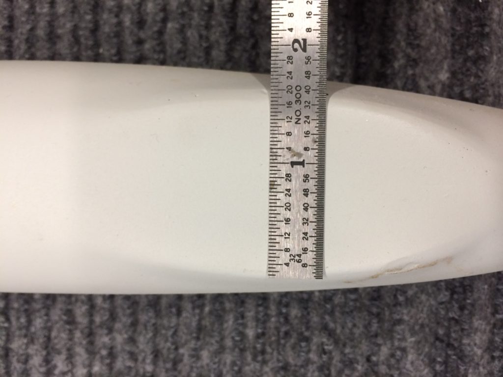
Rudder Cap Strobe Mounting Area – small, even for the 1.74in wide MiniMax Light
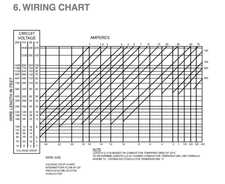
Working through the electrical current requirements of the LED rudder strobe against AC 43.13B, I’ve tried to determine the necessary gauge and then acquire M27500 shielded cable to replace the TAF-supplied PVC jacketed wire in the kit. Based on actual experience with such wire in my Warrior, I’m not impressed with its suitability for aircraft applications. Based on my calculations, I think readily available 22 gauge conductors would be sufficient to handle peak current less than 3A over a run of 20ft. But, based on some data from the awesome builder I mentioned earlier, it’s possible that 20 gauge wire would be a better choice. I ordered some M27500-20TG4T14 from WireMasters. The minimum order was 100ft. This wire may turn out to be overkill for the small LED light. We’ll see.
You’ll find a chart like this in AC 43.13B
The VOR/GS antenna gets built into the vertical stabilizer, so I have to make a commitment to that, even before I’ve settled on my avionics choices. I’m hopeful that conformance with FAA TSO: C34e, C36e, C40c will make my choice compatible with whatever I finally choose for a VOR/GS receiver. Keeping the antenna price down will also make it easier to go with only a GPS navigator. At least the antenna and wiring will be in place. I’ve opted for the Rami AV-520 which has 2.5in diameter base “puck” with removable whips, built-in balun and coax connection.
I’m aiming for an advanced IFR all-Garmin EFIS panel with autopilot. We’ll see where it ends up.
I’ve ordered a bunch of stuff and it will be here next week. I’m perilously close to the official start my Sling 2 build.