As I’ve mentioned before, the fuel system is just short of outrageous. It’s not bad. It’s just that there are plenty of bits and pieces to fit in awkward places, along with the ever present mandate of ensuring the robust integrity of every aspect of the system.
The Sling KAI provides guidance. Careful reading and understanding of the Rotax 912iS Installation Manual is a must. Let’s certainly not forget AC-43.13. All of the information lines up pretty well, yet there’s a lot left to the discretion of the builder.
I’m incorporating all of the fuel system features that appear in the KAI and the Rotax manual, with the exception of a fuel selector bypass check valve for the fuel return line. This valve appears in the Rotax fuel system schematic, but not in the KAI. The purpose of the check valve is to relieve pressure (of residual fuel in the system) to a fuel tank if one or both of the fuel pumps get turned on while the fuel selector is set to off. For now, I’m just going to be careful. But, after 20 years of maintenance experience with my Piper Warrior, I know that I’ve switched on the electric fuel pump [and started the engine] with the fuel turned off. Return pressure is not an issue for the Warrior, but the potential condition of fuel pump on and fuel selector off is common to both airplanes and I’ve already done it – more than once.
Also, as I’ve mentioned in other posts, I’m adding AN6 flare fittings in several places where only barbed fittings were provided with the kit. Key reasons for elimination of the barbs is to avoid awkward conditions for crimping the Oetiker ear clamps and to somewhat modularize sections of the fuel system. To my mind it seems advantageous to have separable pieces that can be unfastened and refastened with wrenches instead of having to cut and then crimp metal clamps. Adding bulkhead fittings for the supply and return lines pretty much demanded flare fittings. Being able to service/replace the fuel filter is another place where swivel fittings seem like they’d be somewhat more conventional and convenient.
The great majority of the fuel fittings are aluminum with just few brass NPT elbows at the fuel selector. Ahead of the firewall, steel fittings are often used, but for experimental applications anodized aluminum fitting are quite common, and as far a I know – not unacceptable. I’m not certain about the metal fuel lines themselves, but Piper put exclusively aluminum fuel fittings behind the firewall and in the wings of my ’84 Warrior II.
The kit provided a big fuel filter with barbs. The engine came with a Rotax part that pretty much everyone that’s building a Sling uses. Me to. The filter really needs to be secured in a suitable location. The sensible and popular location for the Sling 2 seems to be near the battery box. I designed and fabricated a bracket and clamp system.
Another consideration has to do with where to put the fuel pressure sender. Some builders have voiced concerns about making sure that the wet/pressure port faces down, to prevent pooling of fuel in the sender and orifice. I don’t know how big an issue that really is, but I found a place to put the sender and keep the port facing down. More AN6 fittings are involved. I designed and fabricated a bracket and attached the assembly to the engine mount with a cushioned clamp.
One of the things I’ve done is to upgrade the fuel hose. The kit provided SAE J30R7 hose for low pressure fuel supply and return lines. SAE J30R9 fuel injection hose was provided for the high pressure lines between the fuel pump an the engine. I’ve replaced all of the R7 hose with R9. The R9 hose has low permeability and resistance to methanol. There’s also R14 hose. It seems to be somewhat more available, but samples I’ve found are noticeably stiffer than R9 and I believe the pressure rating of the R14 is about half that of the R9. The R14 hose would probably be adequate, but I’ve gone exclusively with the R9.
I’ve built several of the short lines with connectors and firesleeve. I found push-lock fittings specifically for 5/16″ hose. Assembly with those fittings is easy. The ear clamps are solid.
The 5/16″ hose and and several of the fittings – especially the 1/8″ NPT fittings – are a bit on the narrow side. So franky are some of the barbed fittings supplied with the kit. I’m under the impression that the small variations I’ve made will not introduce inadequacies in the feeding of the miserly 912iS, even at full power. If it were a 914 or 915iS it would be a different story. From what I can see, I don’t think I’ve changed the game. I’ll test carefully, you can bet on that.
The fuel system also incorporates a tiny pressure relief channel between the supply and return lines that allow the high pressure side to bleed down into the return circuit when the [engine and] fuel pumps are turned off. Rotax shows this before the fuel filter, but the Sling 2 KAI shows it after. After lots of consideration, I think I’ll go with exactly how the KAI depicts it, using the T-fittings that were provided. I did however, purchase a clever manifold part from Lockwood Aviation that I’d seen on another builder’s blog. Since then I’ve seen the same part used on several Sling builds. The part incorporates the orifice for pressure relief, NPT threaded input and output fittings for pressure and return lines, and also a place to attach the fuel pressure sender, but all at the cost of more fittings that, in close proximity with the fuel filter and another check valve, presented an awkwardness that I don’t care for. I’ve decided not to use the Lockwood part.
Dealing with firewall penetrations is a subject with seemingly endless discussion. It’s a good topic, I’ll admit. The kit came with a big hole in the firewall and 2 halves of a cover plate. This is where avionics power and engine management cables go. The KAI makes a brief mention of the plate and setting some rivnuts, but not much more. I ended up making a sort of gland out of scrap silicone engine baffle material. My Warrior has the same thing where throttle and mixture cables penetrate the firewall. I replaced those cables some years ago. Piper used a paper-like material, but it had seen better days. The silicone material proved to be an excellent replacement for the Warrior. I’ve used the same material here. I’m not done with. It still needs to be sealed. But, it’s basically what I think I want.
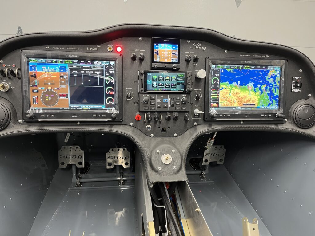
While I’m working to get the FFW tasks finalized, my priority is getting the glare shield/dash, forward fuselage top-skin and windscreen done. I want the panel in final position and completely working before I do that. For confidence testing, I’m connecting up all of the power and grounds for the fusebox and engine.