Monthly Archives: July 2020

Fuselage – Off of the Shipping Stand

Finally — the fuselage has been freed from the heavy wooden stand that secured it within the sea shipping container. My small but mighty workforce – buddy Charlie, my wife Mary Ann and I – managed to lift the fuselage off of the stand and place it on blocks, supported by a workbench. Hooray!

In hindsight, I probably should have cut down the legs of the stand at the tail – before dealing with the front. The blocks keep the front and rear level and about the same height as it had been. It’s a little precarious, but it’s only supposed to be for a short time – until I get the main landing gear attached.

Getting the landing gear into position wasn’t too difficult, even though the landing gear is rather heavy. I was able to use a hydraulic floor jack to lift it into place and insert a couple of through-bolts – all by myself.

There’s a tip in the construction manual about the factory using “pointed” bolts to lead the way for the the actual mounting bolts. I ground down the threads to make rounded and somewhat tapered tips on two extra bolts I happened to have. This made it relatively easily to just push the bolts through the steel brackets and the landing gear. That’s very encouraging and I’m hopeful that inserting all 4 mounting bolts will be doable.

Unfortunately, there is more gap than I think there should be between the landing gear and the faces of the steel mounting point brackets where four 8 x 175mm through-bolts will pull everything together. Measuring the thickness of a stack of scrap aluminum sheet inserted into the gap, I was able to determine that it’s 2.5 to 3.0mm.

I checked with the factory and they say the gap should be 0.0 to 0.5mm. This excess-gap issue is apparently not uncommon, yet somehow remains undocumented. They offered to make me custom laser-cut shims. I appreciate that. Hopefully it won’t take too long to get them. Meanwhile, I’m reluctant to do much while the fuselage is perched on the blocks. I wouldn’t be happy if it were to roll forward or backward. Crunch!

Not having the fuselage sitting solidly on the landing gear is going to hold me back from working in the center-fuselage area to mount controls and linkages. I don’t really have the inclination and wherewithal to build a fuselage “rotisserie” like some aircraft builders do. And, I don’t have ready access to enough warm bodies to muscle the fuselage around the shop, putting it on it’s side, et cetera. At this stage, I still have some other things to work on.
LH Flap – Prep and Assembly

As I near the end of dealing with fitting skins to structure, my confidence was pretty high that this would go well for the flaps (and eventually the ailerons). I’ve learned important lessons about how to inspect skins for proper fabrication – especially bends.

As I discovered from the building the empennage, lengthwise bends (folds) of the skins must be very close to perfect or else entire structure will be pulled out of true alignment when preparing or attempting to close up the final assembly.

There has proven to be considerable lead time in the process of securing replacement parts and the earlier a problem is discovered, the better. Almost immediately after the main QB kit was delivered in February, I looked over the flap and aileron skins – very carefully – and determined that they’d likely be acceptable.

Outdoors metal preparation with Alumiprep 33, Alodine 1201 and then rattle-can primer is much more convenient and pleasant with the warm summer weather. I opted to use NAPA 7220 gray self-etching primer, as none of the surfaces would be exposed. I had the stuff on-hand, but find that I don’t like it as well as the Rust-Oleum product, if for no other reason than the performance of the spray can. The any-angle can from Rust-Oleum is superior, even though I paid considerably more for the 7220 primer. (As I’ve mentioned before, if I do another build, I may well forgo alodine and primer altogether. With my budget and facilities it has been a huge time sink and perhaps not worth the effort. Even at my tender young age, I’ll be pushing up daisies before corrosion would be an issue with an untreated airframe.)

Due to a shortcoming with the listed shipping quantity in the wing kit packing list (KPL), I received only enough 4.8 x 15mm rivets to assemble one flap. I also found that one-size-fits-all — didn’t. It turns out that the overall thickness of one parts stack-up was very slightly less than the recommended grip length of the 15mm rivets. Even though there was no mention of this issue in the assembly instructions, it became obvious that a 10mm length would be better.

I ordered more rivets – both 15mm and 10mm lengths – twice. Once from TAF USA and then from a supplier of Gesipa rivets in UK. TAF sent a big batch of 10 and 15mm rivets to me overnight. Bravo! Great support effort! Thank you!! But, the rivets were not to my liking. They are some alternate brand, different design, slightly larger diameter (didn’t fit) and not nearly as well finished as the Gesipa product. I ordered the real deal, but it took 2 weeks to get them in-hand.

Engine, Propeller and Firewall Forward Kit – Ordered

I can see the end of the airframe assembly down the road and setting the wheels in motion to have the engine group arriving in 3 months or so, will keep me motivated to accomplish tasks in order to be ready when it all gets here.

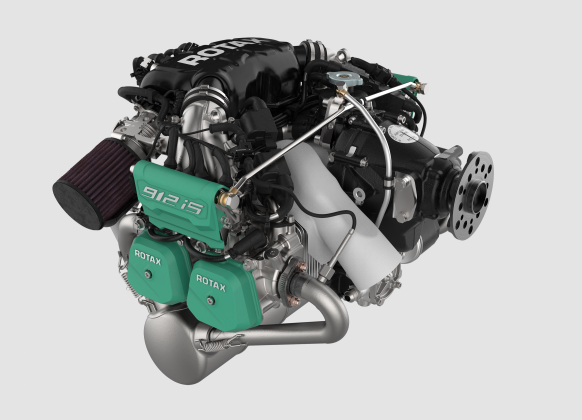
The engine is the BRP Rotax 912iS Sport. It’s state-of-the-art. I’m absolutely set on having a 21st century engine for a 21st century airplane. It’s a mere 100 horsepower, but it’s the engine for the Sling 2 – IMO.

Yes, there is a 115 horsepower turbo engine option – which offers more performance to be sure, but it’s significantly more money, it’s got a turbocharger to maintain, not quite as high-tech – doesn’t have FADEC (computerized engine management system), plus – it demands a constant-speed propeller that costs 4 or 5 times as much as the fixed-pitch unit I’ve decided on for my machine.

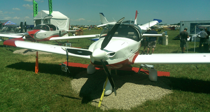
Speaking of propellers – the propeller of choice for the 912iS powered Sling 2 happens to be the very sharp-looking, carbon fiber, 70 inch diameter, 3-bladed, ground-adjustable Whirlwind GA-RW3B, dressed with the perfect spinner.

Sling 2 Aircraft Fitted with Whirlwind Composite Propeller

The engine comes from BRP Rotax in Austria, through their South African distributor – Sling Aircraft and then to the USA. Eventually, it all has to make its way to the Upper Left Corner, where I am, in out-of-the-way Sequim, Washington. It’s a roundabout, slow-boat process – no doubt about it.

Because the engine and aircraft are of African decent – I’m expecting the engine fittings are going to be metric, as opposed to UNF – more typical for aircraft in the US. The engine itself is metric, but I understand that they can be had with UNF fittings for oil and fuel lines. However, the firewall forward kit is going to be for a metric engine and I’m not going to try to swim upstream. Go with the flow. Someday, if it really bugs me I could probably convert it from metric fittings. In the meantime, I’m going to put it all together and go flying – as it comes.

It’s pretty darned exciting and really something to look forward to.

Fuel Tanks – Pressure Testing

Hooray – the fuel tanks seem to be sealed! That’s fantastic because if they weren’t, just about any rework scenario would be ugly. Thankfully, I don’t have to go there.

Having an active build community that shares experiences is so incredibly valuable. I think it’s absolute essential for the growth and long-term success of any kit manufacturer. Fortunately for home-builders of Sling Aircraft, there’s a steadily increasing number of builders and contributions to the knowledge base. That’s where I found the details of employing a water-manometer for safely and confidently testing the integrity of the fuel tanks. Thank you fellow Sling 2 builder — Pascal Latten: Sling2 Fuel Tank Leak Test

My test apparatus was not anywhere near as well-done as Pascal’s, but it worked – once I got the apparatus itself to not leak. At first, I was testing the apparatus. It failed miserably. Once I eliminated all of the leaks caused by clamped hose connections, I was eventually able to get to the point of testing the tanks themselves.

Over a test period of several days, I logged tank pressure vs. temperature and local barometric pressure readings. In theory, you can then compute a leak-rate value that can be compared to an established value (found in a reference table) that is acceptable for whatever you’re wanting to keep in your tank. In this case it’s gasoline.

I ran into a bit of a snag with my barometric pressure readings. After being astounded how little the barometric pressure readings were changing over the test period, I discovered that my home weather center was more for decoration than practical use. The old – thump on the glass trick – revealed that the mechanical pressure gauge was sticky. That pretty much trashed my data. But, all was not lost.

I’d casually kept eye on local barometric pressure, through local weather reports, and it really wasn’t changing a whole lot. It stayed within a rather narrow range. Temperature went up and down – and so did the tank pressure readings – quite a lot! It was somewhat frightening. Do I have I leak, I wondered? But throughout the tests, and ultimately, the ending tank pressure matched starting pressure at the same temperature. I felt good about that – perhaps even better than I might have felt about the subjectively assessing the relative size of an inflated balloon or nitrile glove. In the end, I didn’t bother to compute a leak value for either tank, but I have confidence that it’s all good to go!