Category Archives: Avionics

Glareshield/Dash and Instrument Panel

I’ve been working hard to finalize work behind the instrument panel before I permanently close up the area and bond the windscreen in place. Once that happens, any work behind the panel will have to be done though the openings where the GDU 460 displays go. I could possibly remove the whole panel from the dash, but it’s really and truly so nestled into place that I don’t want to disturb it. Disconnecting it, reconnecting it, pulling it out and fitting it back seems more challenging than I want to contemplate — or actually deal with. Get everything right before it all gets locked down – that’s the plan.

Instrument Panel Powered Up with Engine Information System (EIS) Displayed

The fuselage top-skin on my factory QB came partially riveted in place. I removed it. I also dimpled the skin and the rib to accept 3,2 x 10mm countersunk rivets. The parachute compartment cover skins will eventually go over the countersunk rivets, to be held in place by just a few domed rivets and slotted “fingers” at the edges of the cover skins. I’ve put the top skin back into position with clecos. The dash has been positioned and match drilled with the skin to accept 3,2 x 8 mm domed rivets. The lip of the dash is bonded to the skin with very sticky double-sided tape – supplied with the kit. The next step is to pull the rivets on the lip of the dash.

Once the dash lip is riveted, it’ll be time to fit the windscreen. The windscreen has to transition from outside to inside. The dash does the same thing. The windscreen needs to go between the dash and the skin at the edges. It’s going to be tight. I probably won’t rivet the skin until, or even perhaps after, I do the bonding process for the windscreen with Sikaflex adhesive.

Before bonding, the windscreen and support arch must be fitted with the canopy. The windscreen will almost certainly need to be trimmed along the rear edge of the arch. It’s all going to be very delicate and require great care. If I crack or otherwise damage the plexiglass windscreen it would likely be many months before I could get another one.

At this point, I’ve managed to get the panel and dash positioned and connected to the harness. The wiring looks crazy. Ok, it is crazy. But, it’s pretty much the nature of the beast. This is a custom plug-n-play harness that’s essentially one piece. I laid it into the CF like a sleeping octopus. There’s extra craziness because of how much stuff I’ve got to connect. I think the only way to make it any neater would have required building the harness on the airplane. That just couldn’t happen. As it is, I’ve got all of the various “tentacles” dressed and secured about as naturally and as stress free as they can be. I’m very happy with it, even if it looks rather wild. There’s a lot there.

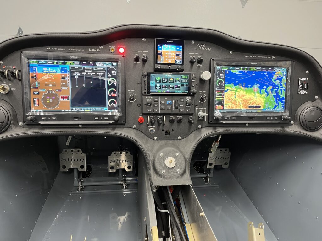
I’m delighted to report that once again, the panel has life. This time, the Engine Information System (EIS) is active. The sensors seem to be working. There are still things that aren’t connected yet. But for the things that are, it all looks great and my confidence is high.

So far, working the flap control, hearing the actuator run and seeing the indicator change is my favorite thing. The VP-X Pro and the G3X Touch integration seem nice. Working the radio frequencies and the remote audio panel is very cool. Both radios transmit and receive. The headset jacks are working, but I haven’t been able to try the LEMO connectors yet. Navigation, position and strobe lights work. Cabin lighting works. Oh so nice.

I’ve got to say, it’s more than just a little exciting. Build on!

Fuselage Tasks – Cables, Wire and Lines

For an E/A-B project there’s a seemingly endless list of small tasks. Some things are simply items in the KAI. Other tasks are things that come to mind as you think about how its all going to come together. Task creep just seems to happen. As long as it doesn’t get out of hand – it’s a good thing.

There is a daunting amount of wiring to support the avionics I’ve elected to squeeze into this airplane. Frankly, I’ve gone overboard. On the other hand, I’ve got all of the makings for a technologically advanced airplane (TAA), extremely well equipped for IFR training and cross-country adventuring. Finding good ways to dress and secure the wiring bundles is important. I’ve put a lot of thought into it and determined that an extra bracket will help me keep the harness up and out of the way. I designed and fabricated one.

Many things have to be squeezed into available space without undue conflict. Wiring, fuel lines, pneumatic lines, brake lines, valves, linkages and such. While there are plenty of best practices for how to do things in airplanes, finding ways to apply them to all of the situations that present themselves is what keeps this amateur builder scrambling for ideas. There’s always something new to learn. It’s fun. Challenging, but fun. Yes. It is. I think.

The fuel-injected Rotax engine has a somewhat complex fuel system. The fuel lines have a fuel supply circuit and a fuel return circuit. When you add filters and a duplex fuel selector and physical considerations, the plumbing details border on outrageous. How I do it is up to me. The KAI supplies only general information. I’m also introducing AN6 flare and push-lock swivel fittings in several places where barbs and ear clamps were originally called out and supplied. Figuring out where and how to mount and connect many of the fuel system components is ongoing.

Some tasks just need doing. Then they’re done. Cutting coax cables to length and adding connectors is straightforward enough. Done. The Rotax 30A Regulator B needs a heat sink that calls for the regulator to move from the fusebox to a nearby location on the engine mount. Done. There are a couple of GPS antennas for the PFD and G5 flight instrument that found homes on top of the GAD 29, above the center avionics stack.

Brake lines need to be routed. The time to do it was now. One line goes from the brake fluid reservoir, through the firewall, to just under where the throttle and brake quadrant is located. From there, another line originates at the pressure side of the master brake cylinder an runs to a compression T-fitting under the console compartment. Two other lines run from the T-fitting, down the main gear legs to each wheel. The combination of the 3 lines and the T-fitting were challenging to place. I should have done it earlier, when access was better. It’s done now.

I received some [evidently] old-style mounting hardware for the parachute activation handle, so I ended making a small bracket to secure the activation pull-handle to the back of the instrument panel. It’s nice. It’s done. My design turned out to be a slightly improved version of a bracket I eventually saw in a photo from the factory. Great minds think alike.

It was time for pneumatic lines to go in. I found a really nice way to route them from the left wing root, though the center console and up behind the instrument panel. Because I’ve seen that the Sling TSi documentation now shows 2 static ports, I added a second one in front of the LH fresh air NACA duct. Both of the equal length static port lines arrive at a push-to-connect T-fitting at the center console. A short line runs from the first tee to another T-fitting that provides two more equal length lines to the the G5 and to the GSU 25C ADAHRS unit. The pitot line has a single T-fitting that also splits between G5 and the GSU 25. The AOA line only goes to the GSU 25. All done.

WAAS GPS and COM 1 Antennas

Quite a few Sling 2 aircraft have been built with their GPS antennas mounted on a bracket under the engine cowling. That’s how the factory used to do it. Now guidance has been changed and a location on top of the rear fuselage is preferred. The new location reportedly offers consistently better reliability. I want reliability for IFR flying.

It was no simple task to get RG-400 coax cable for the GPS routed – and satisfactorily secured – on its way from the top-rear of the baggage area, down and then forward along the bottom of the rear fuselage to the center fuselage, and on to finally arrive behind the GTN 650Xi on the instrument panel. It’s done and it worked out very well.

Dealing with the COM 1 antenna coax cable was comparatively easier than for the GPS because the factory-supplied coax was already secured in place, routed from the mounting site on top of the rear fuselage, all the way to the instrument panel area. All I had to do was add the connectors.

The GPS antenna needed holes drilled in the fuselage skin. I used a doubler that came with my panel and harness and the screws provided with the Garmin GA 35 antenna. A TNC 90 degree solder/crimp connector by Amphenol made for a tidy connection at the top rear of the baggage compartment. A section of vinyl hose, covered with black heat shrink, provides good protection and satisfying aesthetics where the coax passes through the bulkhead, into the rear fuselage.

The COM 1 antenna needed 4 existing mounting holes to be expanded, in order to accept setting of rivnuts. The KAI called for M4 but the Rami antenna, supplied as part of my custom avionics package, came with 8-32 screws. I decided to set 8-32 rivnuts into the fuselage for this mounting. The way the coax was secured to the internal fuselage structure lent itself more to a 90 degree BNC connector. Again I selected an Amphenol solder/crimp part.

FFW and CF Tasks

While the engine mount is off, I’m getting firewall forward and center fuselage tasks done that would be more challenging to do later.

I’m not keen about how the factory seems to expect the stiff-wire push-pull cable to go from the instrument panel, through the firewall and then to the heat box on the firewall. As with other firewall penetrations, I’m not content to just stuff the cable through the firewall with a grommet. I’m also not going to settle for having the cable penetrate the firewall at the absurd angle needed to even have a chance of getting to and working the heater box vane. Instead, I’ve designed and fabricated a jack-shaft bellcrank arrangement as an alternative. I’m still going to use the factory-supplied cable assembly – straight through the firewall, a bowden cable clamp and then attaching the wire to a nylon control horn. Another control horn, at the other end of a shaft, translates the push-pull control motion approximately 90 degrees – to be in line with the action needed to work the arm on the heater box vane. I made a couple of brackets out of aluminum angle and mounted the mechanism on the firewall.

Since my QB airframe was built and delivered, the factory has rethought how and where the ELT antenna goes – to just ahead of the vertical stabilizer. It’s too late for me. The structure was changed to accomodate a new mounting bracket and I’m not going to attempt a retrofit. The old location for the ELT antenna was inside the cabin. I’ve designed and fabricated a bracket to mount the antenna inside, just ahead of the rollover structure on the RH side of the fuselage.

Now that I’ve got my hands on the main battery – EarthX ETX 900, 16AH, LiFePo4 – I’ve been able to build and connect 4 AWG cables from the battery terminals to the 12V contactor and to the airframe ground lug. The high current cables are short and tidy.

I’ve had to acquire [standard AN] replacement hardware for re-mounting the engine mount, but this time, along with the front cables for the ballistic parachute. Longer bolts are needed to pass through the heavy cable-attachment tangs. Initially, I didn’t have the tangs. I eventually got those, along with a bunch of other factory parts that should have shipped with the main kit. The cables and the engine mount are on! Good deal.

With the engine mount in place, I’ve mounted the nose gear strut. Some months ago I accomplished fitting of the bushings, retainers and bolts. That made is super easy to just bolt it all together and connect the push-pull rods to the rudder pedals linkage.

I’m still waiting to put the wheels on because the fuselage is that much lower to the ground, making the inside of the center fuselage (CF) somewhat more accessible than it would be with it higher. I’m taking advantage of the easier access while I dress and secure the wiring and prepare parts of the control linkages and autopilot roll servo.

I’m pretty happy with my approach to securing wire harness bundles as they pass through various openings in the CF structure. I found a source for AN743-13 aluminum angle brackets. These brackets are just right for supporting insulated (Adel) clamps around the wire bundles. It was very challenging to drill holes and rivet the brackets at this late stage of the build. I didn’t have the luxury of doing it while the structure was open, sitting on the bench. Nevertheless, the brackets and clamps are in place and they’re pretty nice. I’ve also put some edge grommet in a few places, just for peace of mind.

I’ve previously tested the flap actuator with temporary connections, but now I’ve made the connections permanent with crimped butt-connectors and various layers of insulation and protective armoring. I’ve done checks to insure that the wiring will be clear of moving mechanisms. It all looks very promising and I’m feeling happy about the work.

Another thing I’m pretty happy about was my purchase of a simple jig for drilling nice cross-holes in the control tubes. Beautiful!

More Antennas and Fittings

After giving things a lot of thought, I finally summoned enough resolve to drill some holes in the aircraft skin, and most, where none had existed before. You’ve got to do what you’ve got to do. Antennas, static ports and bulkhead connectors need holes. Now I’ve got them.

Determining the location of antennas is where most of the thought went. I tried to get the transponder blade antenna pretty close to the fuselage centerline – right in the middle as it turned out. Airframe shading and interference between antennas and other equipment are key concerns. The COM 2 antenna is also on the bottom of the fuselage, just behind the rear wing spar carry-through. I tried to keep it as far away as I could from the the transponder antenna and GMU 11 magnetometer. I didn’t get all of the separation distance called for in various installation documents, but what could I do? This is a tiny little airplane — not a King Air. Time will tell if it’s enough. Build on.

All of the antennas are made by Rami and came along as part of the package with my panel, harness and avionics. Some builders have made rather large doublers. For the moment I’m using only the doublers that came with the antennas. I may eventually go beyond those, but for now, everything is in place.

Of the 14 holes that were already in the ELT mounting tray, none were where I wanted them to be. I made 4 more in the tray that allow 4.0 x 10mm rivets, through the fuselage skin and into the tray, without interfering with the plastic case of the ELT itself.

I made an airframe ground lug from a 5/16″ brass bolt and installed it at the location where the KAI called for a 12 AWG avionics ground bus wire to be passed through a grommet in the firewall on it’s way to the negative battery terminal. I’ve decided to have a 10 AWG cable for the avionics ground bus to the lug (inside) and a 4 AWG cable from the same lug, on other side of the firewall, to the battery. I plan to attach a 6 AWG engine [starter] ground cable to the lug as well.

Rubber fuel lines penetrating the firewall through ordinary grommets, as the kit assembly instructions (KAI) call for, didn’t float my boat. I’ve gone with AN6 bulkhead fittings for the fuel supply and return lines. These fittings need smaller holes than the ones pre-punched in the firewall by the factory. I designed and fabricated a doubler out of steel and riveted over the original holes. The fittings are mounted there.

A set of step-drills is absolutely essential for making holes in sheet metal. I’ve got a cheap set but they’ve worked well.

I’ve set M6 rivnuts (with some JB Weld epoxy for good measure) in the fuselage rib, behind the parachute compartment, where the Rotax ECU goes. Getting the 3 large engine wire bundles and connectors in place, given the minimal space remaining with the LRU rack mounted, is going to be super tight. Fingers crossed.

As long as I had rivnuts and JB Weld handy, I decided to rework the Andair Duplex Fuel Selector valve to receive M4 rivnuts and then set them in place. These steps are called out in the KAI.

My factory quick-build fuselage came with not one – but two – static ports in the rear fuselage. However, the factory now says not to use them. They’ve also said they haven’t officially decided where the new location(s) should be either. They think it’s going to be finalized “soon” and anticipate that it’s going to be just in front of the fresh air NACA duct near the front of the fuselage. They sent me a picture and I’ve gone with that location.

The outside air temperature probe found its home in the LH fresh air NACA duct.

Panel Power On Milestone

I’m happy to report that the panel powered up with no apparent issues. All good!

At this point, I’ve got good reason to believe that the avionics and and wiring harness are happy and healthy. There’s still a long way to go, but I’ve got something to hang my hat on.

The engine management and engine information systems aren’t connected yet, but the Garmin G3X Touch avionics are up and running, along with the Vertical Power, VP-X Pro electronic circuit breaker system. Of course this was done during setup and testing at Midwest Panel Builders, but it’s very nice to see it happening – here and now.

I’ve confidence-checked about as much of the harness as I can at this point. I’ll be able to do more when my Rotax 912iS Sport engine is mounted and its Engine Management System (EMS) connected. Stay tuned for that.

Wiring Harness Placement

After careful study of the wiring harness, I think I generally understand how it should be positioned. All of the connectors and each of the individual wires have labels that match the names of the LRU connectors and appear in the schematic wiring diagrams that came with it all. Sweet!

The harness has a central “gooseneck” from which various connector bundles extend. The several sub-harness bundles have been made to reach corresponding LRUs where they are mounted behind the panel. Other portions of the harness extend to places in the center and rear fuselage to connect with lights and autopilot servos.

There are probably several ways that some of the harness extremities could be routed within the center fuselage (CF). Some routes are undoubtedly better than others. I’ve tried to find what I consider to be the most natural – and if you will – most elegant way to dress and eventually secure the wiring, while always considering guidance in FAA AC-43.13-2B.

So far, so good.

In the interest of keeping things both lightweight and tidy, I’ve opted to replace a heavier and bulkier firewall-mounted circuit breaker enclosure with a simple bracket. I also decided to locate the battery and pitot heat power C/Bs and the ammeter shunt on the LRU rack instead of inside the engine compartment.

IBBS Mounting

The navigation avionics and engine management systems each have a TCW Integrated Battery Backup System (IBBS). The backup systems provide essential power in the event that one or both alternators in the Rotax 912iS engine should fail. There are 2 battery power units that have to be mounted someplace. I’ve found a spot on the fuselage rib, behind the parachute compartment that is within comfortable reach of the associated wiring harness connectors.

I thought that the batteries could use more support than they would get, were they attached directly to the rib. I designed and fabricated doubler plates to reinforce the rib. The batteries are fastened to the doublers.

I’ve had to consider that one day the battery units will have to be replaced. It won’t be easy, but I will be able to get to them from the front, after I remove the pilot side display and the remote LRUs and vertical rack that sit behind it.

LRU Rack Fit and Mounting

Most of the remotely mounted avionics will be behind the instrument panel, on a custom designed and fabricated rack. Each Line Replaceable Unit (LRU) has a specific position on the rack and the harness is custom tailored to precisely reach and connect all of the units together, along with all of the other electrical systems in the aircraft.

I elected to have the harness and panel professionally designed and fabricated by Midwest Panel Builders in Lapeer, Michigan — specifically for my Sling 2 and its extensive Garmin G3X advanced IFR avionics suite. While I might have been able to manage the panel and wiring for a modest VFR setup, there was no way I was going to attempt it for this project.

Even with the custom-made harness, rack and panel there is still plenty of fitting and integration for me to do. This is no paint-by-numbers ELSA project. It’s full-on experimental amateur-built — all the way. I can’t wait to begin training for my IFR rating in this aircraft.

The LRU rack is a replacement for the one I received back in April. The original rack was the first of an all new design and needed several refinements.

The new rack needed to be fitted and the mounting points established. The center portion of the rack needed support. I designed and fabricated a bracket. Everything fits nicely.

Cabin and Firewall

With the firewall forward kit and the avionics, related tasks are accomplished.