Tag Archives: drill

Windscreen and Canopy – Initial Fit

Rivets, wires and avionics are friendly territory for me, compared to where I’m headed now. Fitting the windscreen and getting it bonded in position are tasks I’ve been apprehensive about – extremely apprehensive.

Manipulating clear acrylic sheet – Plexiglass and Perspex are brand names – that’s been molded into compound curves of unusual size, is just asking for trouble. I don’t like trouble. Dealing with this stuff is tricky, all by itself. Don’t even get me started about cutting or drilling holes in it. Eventually, I’m going to add sticky gooey pitch black marine adhesive caulk to the mix. That could easily lead to – yes, you guessed it – super trouble!

The time has come. I can’t avoid it any longer.

Because I opted for a factory quick-build kit, it came with the main canopy already trimmed and bonded to its painted composite frame. That’s fortunate because it may well have spared my frazzled nerves just enough to be able to deal with the windscreen.

The initial canopy placement seemed easy enough. Screw holes in the frame aligned with the ones in the slide assemblies. Countersinking of the frame will be needed to correspond with the short M8 stainless steel CSK mounting screws.

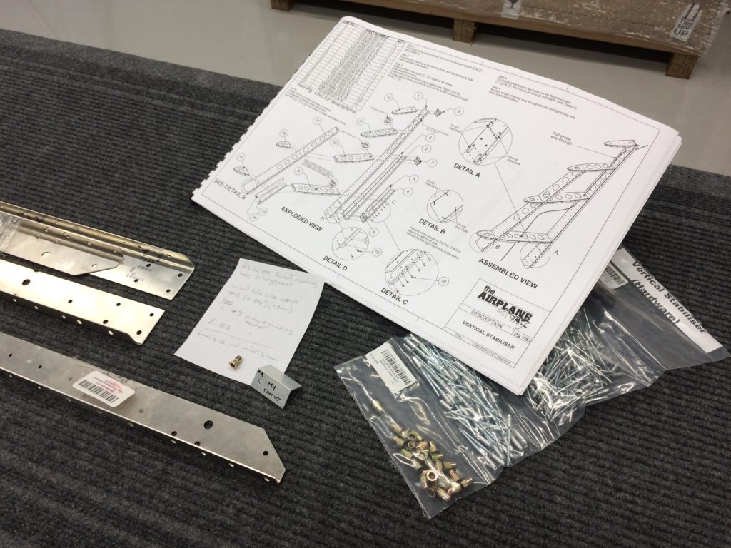
The arched windscreen support frame was fitted and match-drilled to align with M5 rivnuts that were installed at the factory. I made cardboard templates for left and right sides because they’re different. (They shouldn’t be – but that’s how the factory built it.)

The trial fit reveals that the rear edge of the windscreen will have to be cut back by at least 4 or 5 cm to align with the arched support frame. The lower rear edges (corners) of the plexiglass will just barely be under the fuselage top skin when it’s riveted in place. Precise positioning of the windscreen is going to be extremely important to avoid any unsightly gaps between the aluminum skin and the plexiglass.

A latch mechanism has to be fitted into the canopy. I inventoried the latch parts when I received them, but I could not have detected that the supplied spring was not correctly formed. I checked with the factory and confirmed the situation. They’re going to send me a replacement spring.

Windscreen cutting, drilling and bonding comes next.

Process for Rivnut Mounting Hole Enlargement

Before I can accomplish Step 1 in my build, I’ll need to enlarge some holes to accommodate larger M4 fasteners. At some point, TAF changed from M3 to M4 size rivnuts for the vertical stabilizer and other empennage sub-assemblies.

The m4 rivnuts have been supplied with the empennage sub-kit, but the formed parts haven’t been revised to accept them. The build instructions have yet to be updated. Correspondence with TAF confirmed that I will need to do hole enlargement. As the builder, it’s up to me to determine how. This involves tracking down proper tools and developing confidence in a process.

The TAF KAI calls for rivnut mounting holes to be as tight as is practicable and I’ve concluded that a size #A straight flute chucking reamer is the right size to achieve that. This results in the final diameter just under a nominal 6,0mm mounting hole size commonly specified for M4 rivnuts.

I found reaming from #12 to #A size was best done in 2 steps. First, #3 and then #A. This allows the beveled tip of the reamer to align and track nicely with the existing hole as I hold the part by hand and feed the reamer using my drill press at about 750 rpm.

There are also holes for the corresponding screws that will have to be enlarged, once I’ve identified each of them and established what fit clearance is best.

I’ve acquired reamers, developed the process and adequately demonstrated the skills to myself. I haven’t actually started on the build yet, but it feels good to see some aluminum chips in the shop. I’m very close to Build Day 1.

Sheet Metal Training – Closing my Knowledge and Skills Gap

Before I start pulling rivets for real, I’m taking some time to train and practice related skills. There are many useful videos on the Internet. I also found a nice, inexpensive training kit from a homebuilt airplane company in Oregon. I’m signed up for an EAA SportAir sheetmetal workshop – October 26 – 27, at The Museum of Flight Restoration Facility, Paine Field in Washington.

The emphasis of the training resources are centered more on solid rivets and the expectation of somewhat less complete fabrication than what the Sling kits exhibit, but it still seems useful to be introduced to working directly with the metal.

Practice Parts

Before I tackle the training kit – using its materials, I’ve been experimenting with scrap pieces of aluminum sheet and angle, I found at my local Home Depot. It’s a good thing too. I surprised myself as I realized laying out and drilling holes for some short lines of rivets, posed more challenges than I expected. I made real scrap out of my scrap material. I’m learning.