Tag Archives: reaming

RH Wing – Fuel Tank and Inspection Covers

Practice makes perfect they say. Well, maybe not perfect. But the going seems a little easier when you’ve been there before. So it was for mounting the second fuel tank. It actually fit slightly better than the other one. I knew what to do, and on it went without issue.

I did the same basic steps as I did for the first tank. I felt confident, and the work went quickly. I had to carefully dress a number of the overlapping holes in the tank and spar with the #20 chucking reamer in the lithium drill. I knew what to expect and there were no surprises. I also had to touch the holes in spar web to align with the outermost Z-bracket so I could get the AN3 bolts through and threaded into the anchor nuts. Once again, I used a length of cord to pull on the Z-bracket while the tank was being fitted for the final time. That worked like a charm.

There are several stainless steel rivets, top and bottom of the spar near the root. Those are treated with fuel tank sealant for corrosion protection. The rest of the rivets are aluminum multi-grip. Riveting goes pretty fast when the pieces are fitted in place.

Having both fuel tanks mounted is a big milestone and yielded a rather wonderful sense of satisfaction that was sweetened with a measure of relief. Success! Good result. Yay!

The M4 rivnuts for the inspection panels went in without a hitch. I had to enlarge the holes in the bottom wing skin to #A – the perfect size (I’ve found) to accept the rivnut prior to setting them with the drill-mounted tool I use. Screw holes in each of the cover panels had to be enlarged for close clearance of M4 stainless steel button-head hex screws.
LH Wing – Inspection Covers

Compared to mounting a fuel tank, enlarging holes and setting M4 rivnuts seemed easy and definitely less stressful. Still, it was no time to be careless. The wing skin is easy to damage.

It took several steps to get the factory punched holes enlarged to letter number #A diameter, a perfect size to accept M4 rivnuts. I double checked my references and reviewed the process I would use. A series of increasingly larger straight-flute chucking reamers in my trusty lithium-powered drill did the trick.

All of the holes in the wing skin and the inspection covers were in the correct places and the alignments matched perfectly. The drill mounted rivet setting tool worked flawlessly. All rivets are consistent and tight. The screw clearance holes in the covers are ideal. Everything is fits together nicely.

HS Structure Assembly

The horizontal stabilizer assembly started by fitting together 2 sections of rear spar channel with the center section sandwiched by doubler plates – front and back. The result is over 8ft long. Appropriately sized cleco fasteners temporarily hold the parts together. A laser level helps to confirm that the channel is true – straight and free of twist.

The rear channel components were permanently fastened with a combination of 4.0 x 10mm and 3.2 x 8mm pulled rivets. Assembly continued with ribs joining with the front spar channel and clecos hold the front components as they are fitted and fastened in a similar fashion as the rear.

I’ve found that when 2 or 3 parts are sandwiched together with many rivets, it can be a little tricky to get a relaxed fit. Many overlapping holes must align precisely, in order for the rivet shanks to fit through all of the layers easily. I try to take whatever time is necessary to get the best concentric alignment of as many holes as possible, so that little or no reaming is necessary. The kit parts are punched very precisely and overlapping holes will likely line up, given the chance.

My assembly process starts with just a few clecos, while test fitting rivet shanks in many or most of the holes. Then I loosen and reset those few clecos until there is good natural alignment of as many holes as can reasonably be achieved. Eventually, a majority of the holes will line up perfectly, leaving only a very few that may need a little reaming to easily accept a rivet. Straight-shank chucking reamers seem to do a great job. Use the exactly right sizes. #30 and #20 are common.

The HS structure, without skins, is somewhat delicate. I’ve used a couple of stiffeners, from a Vans Aircraft workshop (skills practice) kit, clamped to the innermost HS ribs to provide support while the entire structure is riveted.

The HS structure is symmetrical. At some point, a decision must be made as to which side will be the top and the other side, therefore, the bottom. For my HS, continuity of how the rib flanges relate to the spar channels has turned out to be somewhat better on one side than the other. The side with the best potential for smooth skin support was chosen to be the top. I used a black permanent marker to make indications inside the front spar channel, where they can be seen during the various assembly phases.

With the HS top chosen, left and right HS panels become apparent. 2 Heyco 0.375in snap-bushings have been placed in the rear forming holes of the 2 innermost left-side ribs and anchored with some dabs of gray RTV. The nylon snap bushings are intended to protect the pitch trim servo wire (cable) as it passes through the ribs. I’ve elected to use nylon snap bushings instead of the rubber grommets supplied with the kit.

VS Skin – Prep and Test Fit

I spent several work sessions to make sure I can expect good results when it comes time to close up the VS by riveting the skin to the underling structure. By that time – the VOR antenna, its RG-400 coax cable and the tail strobe wiring must be in place and will be expected to last the lifetime of the aircraft. No pressure!

Holes around the edges of the skin were typically large enough to accommodate 3,2 x 8mm domed rivets, but the holes in the skin at the interfaces with the ribs were smaller and needed to be enlarged with a #30 straight flute chucking reamer. All holes in the skin were carefully deburred. Overall, the concentric alignment of holes in skin and structure were pretty good, but a few will need to be match-reamed during the final fit, immediately prior to the riveting.

The antenna base required 4 recesses be machined into the plastic-like material that allow shortened rivets to fit without interference. My trusty Dremel Tool did both jobs handily – shortening the rivets and creating the recesses.

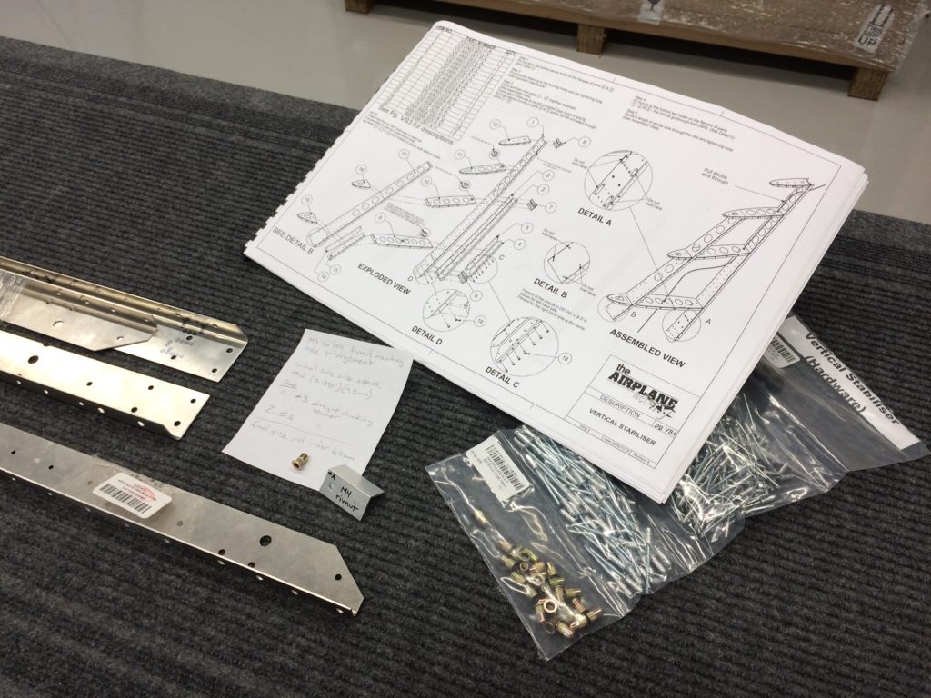
Process for Rivnut Mounting Hole Enlargement

Before I can accomplish Step 1 in my build, I’ll need to enlarge some holes to accommodate larger M4 fasteners. At some point, TAF changed from M3 to M4 size rivnuts for the vertical stabilizer and other empennage sub-assemblies.

The m4 rivnuts have been supplied with the empennage sub-kit, but the formed parts haven’t been revised to accept them. The build instructions have yet to be updated. Correspondence with TAF confirmed that I will need to do hole enlargement. As the builder, it’s up to me to determine how. This involves tracking down proper tools and developing confidence in a process.

The TAF KAI calls for rivnut mounting holes to be as tight as is practicable and I’ve concluded that a size #A straight flute chucking reamer is the right size to achieve that. This results in the final diameter just under a nominal 6,0mm mounting hole size commonly specified for M4 rivnuts.

I found reaming from #12 to #A size was best done in 2 steps. First, #3 and then #A. This allows the beveled tip of the reamer to align and track nicely with the existing hole as I hold the part by hand and feed the reamer using my drill press at about 750 rpm.

There are also holes for the corresponding screws that will have to be enlarged, once I’ve identified each of them and established what fit clearance is best.

I’ve acquired reamers, developed the process and adequately demonstrated the skills to myself. I haven’t actually started on the build yet, but it feels good to see some aluminum chips in the shop. I’m very close to Build Day 1.