Category Archives: Fuselage

Rudder Pedals – Final Fit

Trial fitting revealed that clearance between the arms on the pedal tubes and the hands of the travel-stops, bolted to each opposite arm, was nil. I could actually hear a squeak sound where there was contact, as I worked the pedals back and forth with my hands.

I pondered what to do about it, using my tried and true procrastination skills. As I have no proper equipment for clamping and bending anything heavier than light sheet metal – removing a bit of material from the the lower hand of each travel-stop came to my mind as the answer.

The pedal tubes were removed from the center-fuselage and the travel-stops unbolted from their respective arms. The Scotch-Brite wheel on my bench grinder did a fine job and I was easily able to remove about 1.5mm of material from the lower hands of the travel-stops to open up a satisfactory clearance.

The parts were reassembled and the pedal tubes reinstalled on the floor of the center fuselage. This time around, I installed the upper retainer brackets differently than I had for the trial fit. By now, I’ve noticed what several other builders and the factory are doing. For each bearing, there are a pair of top retainers. Rather than both retainers being together on the same side of the lower bracket, I’ve put one on either side, with space between. That seems to be the way it’s supposed to be. I like it.

Custom Cowl Mounting Strips – Trial Fit

The upgraded cowling strips fit remarkably well. Clecos are in many of the holes at this point and that’s without having to drill anything out. Ultimately, holes will need to be lightly ‘dressed’ with a #30 reamer. This will allow the rivets be positioned and set easily in the 3 and 4 layer stack-up of parts without a fight. The good news is, it’s all a pretty decent situation to begin with.

Earlier I did a little priming of the underside and edges of fastening tabs for the galvanized steel firewall. It’s winter cold outside, and I can’t really do spray painting just now. It was a small hidden area so I brushed on the gray 2-part epoxy primer. It took several days to cure fully. I’ll probably paint the entire firewall, mostly for aesthetics, when the weather warms a bit.

Care will be needed to address some gaps between layers of the parts stack-up. I believe that by removing most (or all) of the clecos across the top edge of the firewall and then riveting around the corner, fitting and pulling one rivet at a time while the pieces are free to move and pull together will allow the gap to close where the rivet is pulled.

I’m planning to install the ballistic parachute and that means I’ll be needing to accomplish some dimpling for most of the holes across the top of CF-RIB-003 and actual countersinking with a 120 deg pilot-cutter, along the top edge reinforcing pieces of the firewall, to accept 3,2 x 8 mm countersunk rivets. More on that in a future installment.

We’ll see how it all goes. Warmer days are ahead.

QB Fuselage Rework – Part 2

Sometimes you have to go backward to go forward. Drilling out rivets is one of those things you have to do sometimes when building and airplane. Fortunately, I’ve had to do very little reverse-assembly. But, there are a couple of parts I needed to add and I’ve opted for an upgrade to the cowling fasteners that calls for replacement of narrow, factory-mounted parts, with wider aftermarket replacements. Drill baby drill!

There’s a reinforcement plate, near where the ballistic parachute rocket canister mounts. The plate rivets to the RIB that forms the back wall of the parachute compartment. Several rivets had to be drilled out and removed so that the plate could be positioned and riveted. Done.

There was also a missing attachment angle for the top right edge of the parachute compartment. It should have been installed at the factory. It’s going on now, but a few rivets had to be removed before the angle was riveted using those same holes.

To go along with the other rework, I’ve opted for an upgrade to the factory-supplied cowl fasteners. I want to use Camloc fasteners rather than the Dzus fasteners that come with the kit. The Camloc parts are more user-friendly when it comes to unfastening and re-fastening of the cowling. For best results, getting the fasteners a little farther away from the edges of the fiberglass cowl is a good thing to do. That involves replacing the factory cowl fastener strips with wider parts that I ordered from Midwest Sky Sports. They make these wider strips and use them for the planes they build and they seem like a good idea to me.

The rivets holding the factory-strips needed to be drilled out. I did it. Now I don’t have that to contemplate anymore. I did a quick fit of the new cowling fastener strips. They look like they fit pretty well. That’s a relief after removing the factory parts.

Rudder Pedals – Trial Fit

The sight of rudder pedals in their proper home makes the whole project seem like it’s on track to be a finished airplane. That’s important for me to realize, now and again, and helps to reinforce the idea that finishing the airplane is possibly doable.

My Sling-branded rudder pedals are an option that I knew about, liked, and deliberately ordered with the quick-build kit. When my QB kit was delivered, the pedal parts I ordered were not there. Most of the related parts I got were for toe-brakes. It took more than 6 months to get things sorted out with the factory and finally get all of the parts for the pedals I ordered — all good now.

The typical braking configuration for Sling airplanes is a simple, single hydraulic master cylinder, lever-operated mechanism that evenly applies the Matco disc brakes for both main wheels. Toe-brakes are a necessity for Sling tail-draggers, but are available as an option for us lowly nose-dragger pilots. Space is pretty tight for 4 independent toe-brake master cylinders with all of the plumbing. From what I’ve been able to determine, Sling pilots find they like the hand-brake, even if they’re used to toe-brakes. I’m going for simplicity. My Piper Warrior has toe-brakes. They’re fine, until they leak all over your pedals and carpet and demand maintenance. I’ve been there, done that and got the T-shirt – thank you very much. Simplicity is a virtue. I’m going through the simple-is-better phase of my life now. You can have toe-brakes in your Sling.

I had hoped that I’d be done with this pedal mounting business – the final assembly. But, it’s turned into a trial attempt. The pedal tubes, bushings and brackets fit nicely, but I did find some clearance issues with the pedal stops that I’ll need to address. That means the whole pedal assembly has to come out again, except for the permanently riveted floor brackets. As I moved the pedals I heard squealing. It’s a little hard to explain, but the edges of the lower hands of the stops can (and do) occasionally touch the edges of the control arms where the nose-wheel pushrods and rudder cables attach. I have to do something. Exactly what, I don’t quite know. Something will come to mind. That’s where procrastination comes in.

Fortunately, I’ve elected to retain the top bushing brackets with M4 x 12mm SS cap screws, washers and elastic stop-nuts. That makes for straightforward disassembly. (I may eventually be forced to use 4mm pulled rivets, if the retainers show any signs of movement, but for now the M4 screws seem reasonable. Space is very tight and riveting would be a challenge – explanation below.)

Typically, the rudder pedal floor brackets, tubes and stops are fitted and mounted much earlier during fuselage assembly, with just the CF floor sitting ever so conveniently on the workbench. For my factory-assembled QB project, this didn’t happen and I’m doing the fitting and assembly work inside the completed CF structure. It’s certainly more challenging to do this work while kneeling and reaching into the cockpit foot wells.

CF – Rivnut Mounting

Setting rivnuts in the center fuselage (CF) area had been on the TODO list for a long time, but it took until now for me to summon up the nerve to actually do the deed. It turned out to be rather easy. I was in the right frame of mind and it all went very well.

A few of the rivnuts are in locations where I couldn’t use my drill-mounted (Astro ADN14) setting tool – particularly one of the M4’s for the A/P bracket nearest the main spar, and two M5’s that will serve to anchor the rudder return springs to the rear spar carry-through member. Fortunately, I’d acquired a nice hand tool (Astro 1443B) and it worked brilliantly for those. Concern about these rivets were what kept me dragging my feet until I’d worked up my courage to attempt the work.

Each of the holes where a rivnut goes, were enlarged to the proper size. This takes several steps, but it’s the same process I’ve used elsewhere. In places where I can’t see the back side of the mounted rivut, I use a mirror to inspect the crimp. They all looked great.

Various panels and covers in the CF that need to be removable, now have their mountings in place.

CF – Control Tubes, Brackets and Bearings

Mounting the control tubes in the center fuselage is very much like the process for the rudder pedals. Once again, clearance and alignment prove to be the main variables.

A couple of important discoveries made a big difference. The first discovery was that the elevator and flap torque tubes are not perfectly straight. They’re close, but they are not absolutely perfect. With an ever so slight bow and four bearing points, over a meter of distance, the centers of the bearing bores present different impacts, depending on rotational position of the tube. The variations are tiny, but if the bearing clearances are too tight – you get a surprising amount of binding.

The other discovery was that not all of the bearings have identical inner diameter. It’s a long story, but I ended up with a few extras and happened to find one that has good bit looser fit on the elevator torque tube.

The bearing with the looser fit proved to be ideal, when I put it at the LH end of the elevator torque tube. Careful dressing of the fuselage brackets and the retainer brackets with the Dremel sanding drum resulted in perfect fits everywhere – and fantastically smooth action.

Careful observation of how the bores of individual bearings center around the tube allowed me to ever slightly shift those centers in good directions as I opened the U-shaped bearing capture areas to eliminate pinching of the bearings around the tube. Each custom fit retainer bracket and bearing is marked for a specific location and orientation. I’m confidently optimistic that there will be just enough clearance for friction free operation after the retainers are permanently riveted.

At the moment, the flap torque tube movement is good, but it isn’t quite a limber as the elevator tube. It’s not of great concern. The flaps are driven by a linear actuator and won’t be anything I notice in the hand controls, which will be effortlessly smooth.

The two main control stick tubes are each supported by a pair of bearings along the roll axis. The front bearing is captured by brackets with U-shaped retainers, top and bottom, that are rigidly riveted to the structure at the front of the main wing spar carry-through.

The upper retainer should have been riveted before the carry-through structure was mated with the surrounding center fuselage members. This is another instance of the factory failing to comply with documented assembly details.

I can’t really get good enough access for confident pulling of 4,0 x 10mm rivets, so I’m going to use screws and elastic stop-nuts for the uppermost holes and (probably) use rivets for the balance of bracket mounting holes. I’ve got to end up with good alignment and enough clearance so that the bearings don’t bind when the brackets get pulled down. I’m certain that the retaining brackets are going to shift slightly from their un-riveted positions. I might use screws after all. That would make it reasonably straightforward to take it all apart and re-tweak the final fit until I get it right. Absolutely no binding will be tolerated. Smooth, smooth, perfectly smooth – that’s how it will be. Period.

Airplane Noises

As far as I can tell, once an experimental aircraft build project gets to a certain point, there’s a right-of-passage that must be embraced — sitting in the thing. Today is the day.

I made a work platform from wood. It fits inside the fuselage on either side. I can sit on it, if and as needed.

Rudder Pedals – Tubes, Brackets and Bearings

Work in the center fuselage continued with trial fitting of the rudder pedal tubes. It’s looking good. Initially, the pilot-side (LH) mounting brackets were easily positioned and the 4,0 x 10mm rivets dropped easily into most of the holes. And, after clearing a bit of paint in the holes, the rest of the rivets fit as well.

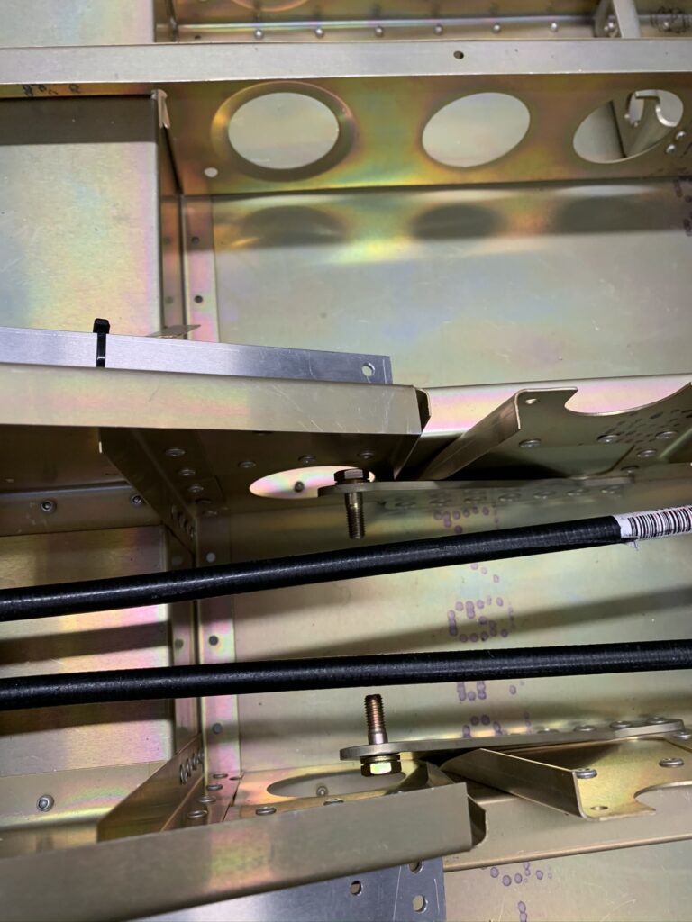
The flight control linkages rely heavily on composite Vesconite bushings, or bearings, depending on how you want to think about their purposes at different places around the airframe. I’ve known for some time, after reading accounts and watching videos posted by other Sling builders, that getting smooth, friction-free action of the controls takes some care. Some folks use the expression – black magic.

These bushings are supposedly designed to be self-lubricating. That’s all well and good, but I know some builders have resorted to supplemental lubrication. I’m trying to avoid greasy, oily, dirt-collecting areas inside the cabin if I possibly can. I’m having some luck – so far.

Two key factors need careful attention – clearance and alignment. Having enough, but not too much clearance, makes alignment slightly less critical. Buttery smooth operation, without additional lubrication, seems to be achievable.

Opening up the U-shaped retainer areas in the floor brackets and the top caps, so that no squeezing of the captured bearings occurs, makes all the difference. I used a small sanding drum on my Dremel tool at a low RPM setting. Eventually, I was able to capture the bearings in the brackets without causing any pinching of the bearing around the pedal tubes.

Next, I used some fine sandpaper around a piece of dowel to relieve a small amount of material from the bearing’s inner surface, particularly at the edges of where a saw had cut them in half. They were once circular and then cut into halves. Some cuts were better than others, but it’s not unusual to find a slight overhang from one or both halves that narrows the bearing bore at the seams where the halves meet when they’re captured in the brackets. Just a slight amount of narrowing can cause binding.

After repeated cycles of fitting and filing, the result is smooth, friction-free operation.

The rudder pedal tubes came nicely coated with gray primer. Areas on the tubes were masked from paint where the bearings ride. Except – one of the masking areas is misplaced by 1cm. I’d read about this, and sure enough, when I measured I found the off-by-1cm error too. The Vesconite bearings are designed to ride directly on the steel. Relatively soft paint would likely gum up the bearing and defeat the self-lubricating properties. I put some protective masking tape around the tube and used a strip of fine sandpaper to precisely remove additional paint.

Last, but not least – I can see how the Sling-branded rudder pedals are going to look. I think it’s much cooler than the plain T-bars. It took almost 6 months after my quick-build kit was delivered to finally get all of the pedal parts. That was a full year after I’d placed my quick-build order, which included the option. All’s well that ends well.

The Sling-branded pedals are essentially the same as the ones for toe-brakes, except that they are mounted on the standard pedal tubes and the hand-brake configuration is used. The toe-brake option has different pedal tubes, different brackets on the floor and no hand-brake. I know because I got a bunch of those parts. I worked with the factory and eventually got all of the parts I actually needed for my pedals.

Rework Outer Seatbelt Brackets

Any work on and in the center fuselage is part of a big step forward. In this case, the work is actually rework, owing to one of several shortcomings introduced during the factory quick-build of my fuselage – which evidently was a bit hasty. TAF admittedly rushed to ship in the last hours before a three week holiday shutdown. Let’s just say there were a few shortcuts taken.

There was a general class of shortcut that I’ve found several examples of – riveting places and parts that shouldn’t have been until other steps were completed. The most vexing examples were the seatbelt anchor brackets being mounted without the AN5-5A bolts and washers in place. I’d noticed this very early on after delivery and have been troubled ever since about how I’d be able to get things as they should be.

As I mentioned in my last post, I finally overcame a mindset that I’d have to drill out and re-rivet the center brackets to place the bolts. With courage and great care I was able to flex my way to a happy result. The outer brackets demanded the drill and re-rivet approach. That has proved very doable, especially since I’ve got the fuselage solidly down on the floor where I can work on it without concern about toppling. Yay again!

I’ve gained some valuable experience with drilling out the big 4,8mm rivets from my rework of the aileron and flap hinge bracket sub-assemblies. With a #12 bit in my lithium battery-powered drill I was able to get the outer brackets off cleanly. And when the time comes, I’ll be able to rivet them back on – with the bolts in place. Glad I don’t have to worry about this anymore.

Fuselage Sitting on Main Landing Gear

It may not seem like a big deal, but having the fuselage safely off of the workbench, where it had been (somewhat precariously) perched, is a great relief and a meaningful milestone. It’s now in a position where I can work inside the center fuselage – comfortably and confidently.

The fuselage spent months sitting on the wooden structure that held it inside the sea shipping container. Then it sat for weeks on a workbench and up on some blocks that I was constantly concerned might cause great damage if the structure should somehow roll forward or backward on those blocks.

With the main landing gear in place and some help from my wife and also from my friend Charlie, the three of us were able to remove another wooden shipping structure at the tail, clear the blocks and the workbench from underneath the center fuselage and set the whole business down on the floor. The tail is supported by a padded sawhorse. Joy! Joy!

I’ve been waiting for months to work inside the center fuselage. I did the first bit of work right away – installing the center seatbelt anchor bolts into the brackets where they should have been placed by the factory – before the brackets were riveted to the CF structure. It’s clearly called out in the construction manual, but the step was forgotten.

At first, I thought I would have to unrivet both center brackets in order to get the bolts into position. But, I eventually became hopeful that I could flex the brackets just far enough to slip the bolts in. Yes! It worked. Good thing too, because it really would have been nearly impossible for me to re-rivet the brackets with conflicting structure in the way. I’m so glad I went ahead and attempted positioning the bolts as I did. Done!

I have the same factory-forgot-the-bolts issue with the outer anchor brackets, but at least there’s ample space to drill out and re-rivet. There’s no way I can flex those outer brackets enough to get the bolts where they need to be. The structure in that area is far too stiff.